


Services on Demand
Journal
Article
 English (pdf)
 Article in xml format
 Article references
 Send this article by e-mail
Indicators
-
 Cited by SciELO
 -
 Access statistics
Related links
-
 Similars in
SciELO
Similars in
SciELO
Share

 Permalink
Portugaliae Electrochimica Acta
Print version ISSN 0872-1904
Port. Electrochim. Acta vol.37 no.5 Coimbra Oct. 2019
https://doi.org/10.4152/pea.201905295
ARTIGOS
Potentiostatic Co-deposition of Nickel and Graphite Using a Composite Counter Electrode
B. Aremoa, M.O. Adeoyea and I. B.Obiohb
a Department of Materials Science and Engineering, Obafemi Awolowo University, Ile-Ife, Nigeria
b Centre for Energy Research and Development, Obafemi Awolowo University, Ile-Ife, Nigeria
ABSTRACT
Nickel and graphite were potentiostatically co-deposited using a nickel-graphite composite counter electrode (HCE) with tunable-friability. Graphite electrodes were produced at densities of 0.920, 1.026 and 1.188 g/cm3, and their suitability for constitution into HCE was assessed. The surface area of the nickel component was varied from 100% to about 60% and 30 %, and combined with the graphite electrode, to form HCE, designated as triplet, doublet and singlet, respectively. Deposition was done for about 8 hours in 1 M NiSO4, using the different HCE constitutions, an Ag/AgCl reference electrode and a custom deposition head which served as working electrode. The mechanism of graphite electrode unraveling was observed to be the formation of oxygen and CO2, due to oxidation reactions at HCE. The graphite electrode with a density of 0.920 g/cm3 was selected for HCE, due to its extensive surface porosity, a characteristic determined as favorable to the mechanism of electrode unraveling. Co-deposition of graphite with nickel was observed to increase as the nickel surface area was reduced from triplet to singlet. SEM micrographs show partially and fully embedded graphite particles in the nickel matrix, while the presence of nickel and graphite was affirmed.
Keywords: electrodeposition, nickel, graphite and optical microscopy.
Introduction
Electrodeposition has remained an attractive route for the synthesis of materials and complex structures, due to its relative simplicity and low-cost setup. Co-deposition, referring to the simultaneous electrodeposition of multiple metallic and non-metallic phases, has been receiving considerable attention lately. It has been used for the synthesis of metallic alloys [1-2], metal-ceramic composites [3-4] and 3D micro architecture [5]. In many of these applications, the galvanostatic or constant current approach is often employed, to achieve precise control of the deposition rate [6]. However, the variously named additives – wetting and leveling agents, brighteners – that are needed to control deposit morphology and deposition current introduce bath complexities. Different atomic interstitial elements or their intermetallic compounds derived from these additives contaminate the electrodeposited films [7]. In potentiostatic deposition, voltage is constant. This confers on the process the advantages of close control of the deposition voltage and bath simplicity, also avoiding the use of contaminating additives. However, in the potentiostatic mode, the deposition current is not constant; it tends to decrease as the concentration of the ionic species decreases in the solution [8]; this makes deposition rate control difficult.
Often, co-deposition involves the use of multi-species ionic baths or solid-particulates in an ionic suspension [9-10]. The latter approach is mostly used for the synthesis of metallic-nonmetallic composite films. However, co-deposition using particulates suspended in a solution is fraught with problems. These stem from the tendency of the particulates to settle in the solution, resulting in the deposits inhomogeneity. Systems for introducing fresh particulates, and keeping them in suspension through bath agitation or the use of surfactants, have been proposed [11-14]. However, the solution agitation under potentiostat control may lead to instability and loss of control of the working electrode potential.
This work reports a method of nickel and graphite co-deposition that avoids the need for continual introduction of particulates and suspension agitation, by using a composite nickel-graphite electrode with built-in friability. The effects of the composite electrode constitution and the optimal conditions of the graphite electrode unraveling were investigated.
Experimental
Materials
Graphite electrode
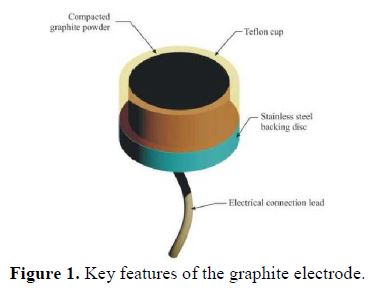
The graphite electrode assembly comprises a Teflon cup filled with compressed graphite powder from a lot of <63 µm powder. The electrode assembly is shown in Fig. 1. Three electrodes compressed to densities of 0.920 g/cm3, 1.026 g/cm3 and 1.188 g/cm3 were produced. The stainless steel backing disc provides electrical contact with the powder.
Nickel electrode
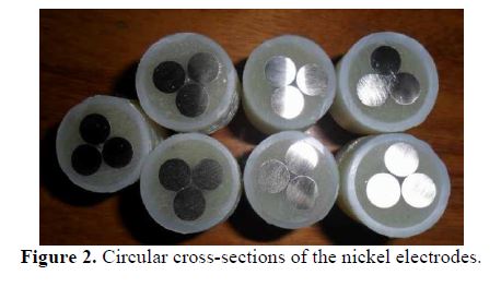
The nickel electrode was formed from three pieces of 15 mm by Ø9 mm sections of nickel (GoodFellow, Pennsylvania). They were electrically connected together, and then mounted with epoxy inside a Teflon cup, in such a way that only their circular cross-sections were exposed. Fig. 2 shows the nickel electrodes with the exposed circular cross-sections.
Deposition bath
The deposition bath was 1 M NiSO4, prepared using deionized water. The bath’s pH was adjusted to a starting value of 2.5, using drops of concentrated hydrochloric acid.
Deposition head
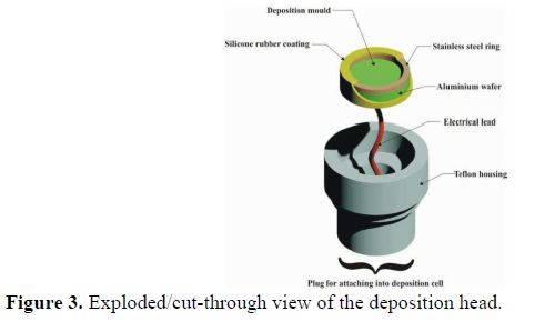
The deposition head assembly is shown in Fig. 3. It comprises an aluminum disk with an attached electrical lead. The stainless steel ring placed on aluminum creates a cylindrical cavity inside which the deposition takes place. This assembly forms the working electrode in the three-electrode deposition setup. Sections of aluminum and stainless steel ring that were excluded from the deposition were coated with air-curing silicone rubber. The aluminum surface was cleaned prior to the electrodeposition, according to ASTM B322 [15] and ASTM B253-87 [16].
Deposition procedure
The exposed surface area of the nickel electrode was varied by coating the electrode surface in the manner shown in Fig. 4. This creates configurations referred to as “singlet”, “doublet” and “triplet”. These were combined with a single graphite electrode to form a “composite” nickel-graphite counter electrode. The composite nickel-graphite counter electrode, the Ag/AgCl reference electrode and the aluminum backing plate in the deposition head constitute the 3-electrode setup for deposition. The deposition was done, whilst maintaining a bath pH of between 2.5 and 3.0, and an imposed potential of –1400 mV (vs. Ag/AgCl).
SEM and optical microscopy characterization
The co-deposited nickel-graphite was characterized using a FEI-Quanta 600 scanning electron microscope and an Oxford EDX detector. Optical microscopy characterizations of the compressed graphite electrodes and the co-deposited nickel-graphite were done on an inverted metallurgical microscope, using the extended depth of focus (EDF) software, Helicon Focus® 5.2.
Theory
The unraveling of the particles of the graphite electrode component of the composite counter electrode occurs due to the formation of oxygen and carbon dioxide gas bubbles at the electrode. The process is illustrated in Fig. 5.
These bubbles grow and eventually “pop out”, causing the compacted graphite particles to spew into the bath. However, for the compacted graphite to unravel, the density of compaction must not be too high to cause coalescing or fusing together of the graphite particles. The reactivity of the graphite surface is enhanced by its surface porosity which provides increased reaction sites.
The spewed-out graphite particles migrate to the working electrode due to electrophoresis, and co-deposit with the growing nickel. The friable graphite electrode thus ensures:
- the presence of sub-micron size particles unravelling into the bath, which cause the electrode gradual reduction in size;
- that there is no need for bath agitation, because the sub-micron sized particles that have high zeta potential are co-deposited by electrophoresis into the deposition mould.
Results
Characterization of graphite electrodes at different compression densities
Optical micrographs at 400× magnification (using EDF) for A, B and C graphite electrode samples are shown in Figs. 6, 7 and 8, respectively.
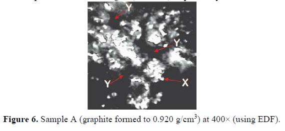
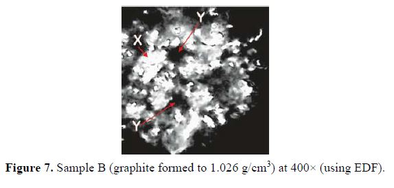
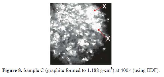
For sample A, formed to a density of 0.920 g/cm3, the micrographs show pores (marked Y in the micrographs) and distinct particles (marked X in the micrographs) on the surface. There is little coalescing or fusing together with the graphite particles. The pores were smaller in sample B, compressed to a density of 1.026 g/cm3, as can be seen in the micrograph (Fig. 7). In the micrograph in Fig. 8, the relatively high density of 1.188 g/cm3 has caused an almost total coalescing of the particles, with virtually eliminated pores.
Characterization of nickel-graphite from composite electrode configurations
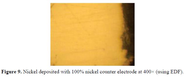
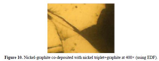
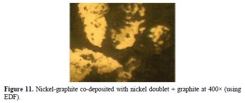
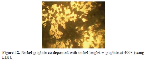
Fig. 9 shows the micrograph at 400× (using EDF) of nickel solely deposited with a 100% nickel counter electrode. Figs. 10, 11 and 12, also at 400× (using EDF), show micrographs of the nickel-graphite film deposited with nickel triplet, doublet and singlet composite counter electrodes, respectively. The deposits produced with a 100% nickel counter electrode show a microstructure free of any co-deposited particles. Fig. 10 shows few scattered specks of the co-deposited graphite. The co-deposited graphite tends to increase, as shown in Fig. 11, by the deposition with the nickel doublet. This increased further for the deposition done with the triplet in Fig. 12.
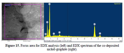
SEM and EDX characterization of the co-deposited nickel-graphite film
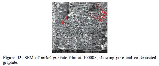
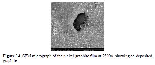
The SEM micrograph of the co-deposited film is shown in Fig. 13 and 14, while the EDX spectrum is presented in Fig. 15. The micrograph shows pores, partly and fully embedded graphite particles in the nickel matrix. Also, the EDX spectrum indicates the presence of carbon.
Discussion
Influence of the graphite electrode density
The influence of the compaction density on the surface porosity of the compressed graphite can be seen in the optical micrographs in Fig. 6 – 8. As compaction density increased, the surface pores reduced and the particles coalesced. This had two main effects on the co-deposition process. Rough, pore-filled surfaces have a higher surface area for reactions to take place; hence, such a surface could be described as more reactive. Also, less unraveling of the compacted particles would occur if the compression density was too high; the goal of graphite co-deposition would thus not be realized at higher compaction densities. Graphite sample A was selected for the composite electrode, due to its low density, and because it exhibited more favorable surface features.
Co-deposition mechanism
In potentiostatic deposition, it is the potential of the working electrode that is controlled by the potentiostat. The controlling current flows through the counter electrode and fluctuates whilst controlling electrolyte concentration, and thus, indirectly, the working electrode potential. If the current fluctuation through the counter electrode was minimal, the potential (negative) at the counter electrode could be considered approximately equal in magnitude, but of opposite polarity, to the potential (positive) at the working electrode. This positive potential at the graphite counter electrode is sufficient to cause its electro-oxidation to CO2.
The –1400 mV (vs. Ag/AgCl) applied at the working electrode is equivalent to – 1200 mV (vs. SHE). In the nickel-water Pourbaix diagram [17], at a pH of about 3.0, the reduction of Ni2+ to nickel takes place at about –260 mV (vs. SHE), while a potential higher than 1000 mV (vs. SHE) is required to decompose water into oxygen at the counter electrode. Hence, the potential of -1200 mV (vs. SHE) was applied, so that its approximate positive mirror at the counter electrode could achieve graphite oxidation.
Nickel-graphite structure
The SEM micrograph in Fig. 13 shows a network of pores created by the co-evolution of hydrogen gas. Hydrogen co-evolution causes pH increases near the region of the working electrode as a result of water’s decomposition and accompanying local production of hydroxide ions [18]. This makes the bath alkaline, increasing the risk of nickel hydroxide production. Hence, a continual lowering of the pH bath with droplets of concentrated HCl to within the 2.5 – 3.0 window was necessary. The micrograph also shows partly co-deposited graphite particles (arrow A) with a size of about 5 µm. Hyam et al. [19] reported similarly size particles as being more favored for electrophoretic deposition, due to their high zeta potential which enables them to remain in suspension for longer. The micrograph in Fig. 14 shows an embedded graphite particle co-deposited within the nickel matrix.
The EDX spectrum shows peaks indicating the presence of carbon and nickel phases. These indicate nickel and graphite co-deposition. The aluminum and oxygen peaks are believed to arise due to the method used for the removal of the aluminum backing layer, which involves its dissolution within sodium hydroxide, while the sulphur peak is traceable to the nickel sulphate bath.
Conclusions
This study demonstrated the co-deposition of nickel and graphite using a composite or composite nickel-graphite counter electrode with built-in friability. The electrode’s friability is tunable by a variation of the compaction density of the graphite electrode and its constitution with the nickel. The mechanism of the graphite electrode’s friability was the formation of carbon dioxide and oxygen at its surface, which unravels compacted graphite particles into the bath. This approach maintains a quiescent bath that favors the potentiostatic deposition approach, and helps guaranteeing deposit uniformity and homogeneity.
References
(1) Zangari G. Electrodeposition of Alloys and Compounds in the Era of Microelectronics and Energy Conversion Technology. Coatings. 2015;5:195-218. [ Links ]
(2) Rudnik E, Wloch G, Czernecka A. The Influence of Potential-Current Conditions on the Electrodeposition of Ni-Sn Alloys from Acidic Chloride-Sulphate Solution. Arch Metall Mater. 2014;59:195-198. [ Links ]
(3) Ahmad YH, Mohamed AMA. Electrodeposition of nanostructured nickel-ceramic composite coatings: A review. Int J Electrochem Sci.2014;9:1942-1963. [ Links ]
(4) Cao Y, Wei G, Ge H, et al. Synthesis and Magnetic Properties of NiCo Nanowire Array by Potentiostatic Electrodeposition. Int J Electrochem Sci. 2014;95272-5279. [ Links ]
(5) Edström K, Brandell D, Gustafsson T, et al. Electrodeposition as a Tool for 3D Microbattery Fabrication. The Electrochemical Society Interface. 2011;41-46. [ Links ]
(6) Eom H, Jeon B, Kim D, et al. Electrodeposition of Silver-Nickel Thin Films with a Galvanostatic Method. Mater Trans. 2010;51:1842-1846. [ Links ]
(7) Brankovic SR, Vasiljevic N, Klemmer TJ, et al. Influence of Additive Adsorption on Properties of Pulse Deposited CoFeNi Alloys. J Electrochem Soc. 2005;152:C196-C202. [ Links ]
(8) Montoya P, Marín T, Calderón JA, et al. Electrodeposition of Polypyrrole Films: Influence of Fe3O4 Nanoparticles and Platinum Co-Deposition, in: A. de Jesus Motheo (Ed.), Aspects on Fundaments and Applications of Conducting Polymers, InTech, Europe, 2012, pp. 137-158. [ Links ]
(9) Hovestad A, Janssen LJJ. Electrochemical co-deposition of inert particles in a metallic matrix. J Appl Electrochem. 1995;25:519-527. [ Links ]
(10) Devaneyan PS, Senthilvelan T. Electro Co-deposition and Characterization of SiC in Nickel Metal Matrix Composite Coatings on Aluminium 7075. Procedia Engineering. 2014;97:1496-1505. [ Links ]
(11) He Y, Wang SC, Walsh FC, et al. The monitoring of coating health by in-situ luminescent layers. RSC Adv. 2015;5:42965-42970. [ Links ]
(12) Mihailovic M, Pataric A, Gulišija Z, et al. Electrophoretically Deposited Nanosized Hydroxyapatite Coatings On 316lvm Stainless Steel For Orthopaedic Implants. Chemical Industry & Chemical Engineering Quarterly. 2011;17:45-52.
(13) Teruyama S, Shrestha N, Ito Y, et al. Plating of Ni/c-BN composite film in two steps. J Mater Sci. 2004;39:2941-2943. [ Links ]
(14) Panitz JK, Dugger MT, Peebles DE, et al. Electrophoretic deposition of pure MoS2 dry film lubricant coatings. J Vac Sci Technol A. 1993;11. [ Links ]
(15) American Society for Testing and Materials, ASTM B 322 – 99: Standard Guide for Cleaning Metals Prior to Electroplating, ASTM, West Conshohocken, 2000.
(16) American Society for Testing and Materials, ASTM B 253 – 87: Standard Guide for Preparation of Aluminum Alloys for Electroplating, ASTM, West Conshohocken, 1987.
(17) Thompson WT, Kaye MH, Bale CW, et al. Pourbaix Diagrams for Multielement Systems, in: R. W. Revie (Ed.), Uhlig's Corrosion Handbook, John Wiley & Sons, New York, 2000, pp. 125-136. [ Links ]
(18) Gabe DR. The role of hydrogen in metal electrodeposition processes. J Appl Electrochem. 1997;27:908-915. [ Links ]
(19) Hyam RS, Subhedar KM, Pawar SH. Effect of particle size distribution and zeta potential on the electrophoretic deposition of boron films. Colloids Surf A. 2008;315:61–65.
Received January 3, 2017; accepted August 12, 2018
E-mail address: bolaji_aremo@yahoo.com

