


Serviços Personalizados
Journal
Artigo
 Inglês (pdf)
 Artigo em XML
 Referências do artigo
 Enviar este artigo por email
Indicadores
-
 Citado por SciELO
 -
 Acessos
Links relacionados
-
 Similares em
SciELO
Similares em
SciELO
Compartilhar

 Permalink
Portugaliae Electrochimica Acta
versão impressa ISSN 0872-1904
Port. Electrochim. Acta vol.35 no.1 Coimbra jan. 2017
https://doi.org/10.4152/pea.201701001
Potentiostatic Electrodeposition of Co-Ni-Fe Alloy Particles Thin Film in a Sulfate Medium
Ismail Hanafi* , Abdul Razak Daud and Shahidan Radiman
School of Applied Physics, Faculty of Science and Technology, Universiti Kebangsaan Malaysia, 43600 Bangi, Selangor, Malaysia
Abstract
The aim of this study was to produce thin films of ternary cobalt-nickel-iron (Co-Ni- Fe) alloy by electrochemical deposition method at different electrodeposition potentials in a sulfate solution (0.15 M CoSO4 + 0.2 M NiSO4 + 0.005 M FeSO4). The Co-Ni-Fe alloy thin films were electrodeposited on indium-doped tin oxide (ITO) coated on a conducting glass substrate. Voltammetric studies indicated the potential range between -1.10 to -1.30 V (SCE) for successful deposition of Co, Ni and Fe. The energy dispersive X-ray (EDX) analysis indicated that the films exhibited anomalous behavior with Ni content significantly increased, whereas the Co and Fe content decreased as the electrodeposition potentials reached more negative values. The scanning electron microscopy (SEM) study showed that the electrodeposited films were uniform for all applied potential values and larger particles were formed when higher electrodeposition potentials were applied. Investigation by X-ray diffraction (XRD) revealed that the dominant phase in the deposited film was amorphous Co-Ni-Fe. Hysteresis curves of the ternary alloy film obtained from vibrating sample magnetometer results prove that the alloy is ferromagnetic. The coercivity mechanism of the Co-Ni-Fe films has obeyed Neel's relation which is thickness dependence.
Keywords: applied potential; Co-Ni-Fe thin films; ferromagnetic; ITO; Neel's relation.
Introduction
Magnetic film of Co, Ni and Fe has high potential for special applications such as in reading or writing heads, magnetosensors and magnetic data storage devices [1]. In the last few years, intensive studies [2, 3] have been done on these materials to explore their unique soft magnetic properties. New soft magnetic materials with greater performance are desirable due to rapid increase of areal density (bits per square inch of recording medium) of data storage in computer drives [4], advanced miniaturization and high capability electromagnetic devices in MEMS [5, 6]. Numerous Co-based ternary alloys such as Co-Fe-B [7], Co- Fe-Cu [8] and Co-Ni-Fe [9, 10] are among the potential candidates to serve the purpose. In particular, the ternary Co-Ni-Fe alloys have been well identified as one of the promising systems due to their high magnetic saturation flux density (BS ∼ 2.0-2.1 T) and low coercivity (< 2 Oe) [11].
Over recent years, the fabrication of Co-Ni-Fe ternary alloys thin film is done through various techniques such as positive microemulsion [12] and electrodeposition [13]. The electrodeposition is a prevalent method among the techniques in producing metallic alloy films [14] as the method is economic [15] with wide range industrial applicability [15]. In electrodeposition method, experimental parameters like electrodeposition potentials [16] and electrolyte condition (composition, temperature, additive and pH) can alter the deposition product properties. In addition, electrodeposition can be conducted using either galvanostatic or potentiostatic technique to produce fine particles of metallic substances.
Galvanostatic deposition technique is able to produce particles with several characteristics in a single deposit as reported by Maksimovic et al. [17] where deposition at low applied current densities has produced copper particles with both massive dendritic structure and 3D ramified structure in the same deposit. As the current density is increased the massive dendritic structure vanished leaving only 3D ramified structure. Therefore, galvanostatic deposition is only advantageous if there are no requirements to control besides the necessary morphology of the product. Potentiostatic deposition technique is essentially used to investigate the nucleation and growth process through current-time transient [18]. For instance, at lower applied potentials, anisotropic branched dendrites were obtained in Cu electrodeposition [19]. The extent of branching of these dendrites was increased at higher applied potentials. However, in contrast to galvanostatic deposition, the morphology of product produced by potentiostatic deposition depends on the applied potential. There is a critical energy for nucleation of a particle [20] which can be achieved via an applied potential. Higher energy will be supplied at a higher applied potential which leads the nuclei to grow and form a specific morphology. Hence, by controlling the applied potential, deposits with desired morphologies can be obtained. Therefore, potentiostatic deposition technique is very suitable to various fields such as in optical and electrical devices fabrication which require specific crystallographic planes [21] where a controlled morphology is vital. In the present study, we intend to fabricate Co-Ni-Fe alloy thin films via potentiostatic mode at different electrodeposition potentials, and study the relation of applied potentials with the morphology and magnetic property of the thin films deposited on indium tin oxide (ITO).
Materials and method
A computer-controlled potentiostat was used as a potential source. A sulfate bath containing 0.15 M CoSO4, 0.2 M NiSO4, 0.005 M FeSO4 and a buffer solution of 0.4 M H3BO3 was used in electrodeposition of Co-Ni-Fe alloy. The solution was adjusted to pH 3 by adding a few drops of 0.1 M H2SO4 solution and all investigations were conducted at room temperature. The electrodeposition was conducted in a three electrode cell comprising a platinum wire as counter electrode, a saturated calomel electrode (SCE) as reference electrode, and indium-doped tin oxide (ITO) coated on glass as working electrode. A polycrystalline ITO (Prazisions Glas & Optik, Germany) coated on glass (10 Ohms/sq) with diameter of 1.50 cm and thickness of 0.11 cm was used to obtain samples for electrodeposition. The samples were first ultrasonically degreased in acetone for 10 min and rinsed in deionized water. Cyclic voltammetry technique was performed using a computer-controlled potentiostat/galvanostat (Voltalab PGZ402, France) to determine the suitable electrochemical potential region for deposition of Co, Ni and Fe. The surface morphology of the films was observed under a field emission scanning electron microscope (FESEM, MERLIN Compact, Germany). The chemical analysis was done using an energy dispersive X-ray (EDX) analyzer equipped to the FESEM. The phase characterization was performed by means of an X-ray diffractometer (XRD, Bruker AXS model D8 Advance, Germany) using a monochromatic Cu Kα1 source (λ= 0.154056 nm) scanned between 10° and 60° with the step size of 0.02°. The magnetic properties were investigated using a vibrating sample magnetometer (VSM, Lake Shore model 7404, USA) at room temperature.
Results and discussion
Fig. 1 shows the stabilized cyclic voltammograms for deposition of individual element of Co, Ni and Fe, and Co-Ni-Fe alloy at potential scanning rate of 10 mVs-1.
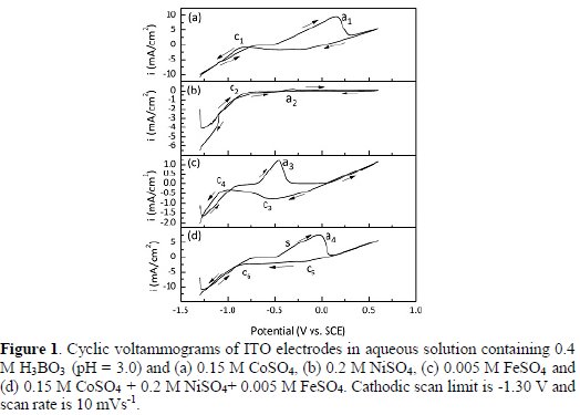
The potentials were scanned from -1.30 V to 0.6 V, in positive direction, and then reversed to the starting potential. The cyclic voltammetry result for a solution containing 0.15 M CoSO4 is presented in Fig. 1(a). Only one single anodic peak (a1) was observed around 0.119 V which corresponds to the oxidation of cobalt metal into Co2+. During the reversed scan a cathodic peak (c1) appeared at -0.875 V which corresponds to the reduction of Co2+ into cobalt metal. This was followed by a further increase in current due to reduction of H+. This result is consistent with a previous study on electrochemical deposition of Co2+ onto ITO electrodes in sulfate aqueous solutions [22]. Fig. 1(b) shows the voltammetric curve of nickel at concentration of 0.2 M where the oxidation peak (a2) is hardly detected, whereas the reduction peak (c2) appears at -0.8 V. A similar observation has been reported by Afshar et al. [23]. For individual iron (Fig. 1(c)) at concentration of 0.005 M, the anodic peak (a3) appears at a further negative region, approximately at -0.489 V, compared to the individual cobalt and nickel. During the reversed scan, it was observed the presence of two reduction peaks, c3 and c4. The first peak (c3) corresponds to the iron reduction from Fe2+ into iron metal at a potential of about -0.5 V which is significantly close to the Nernstian value. Further increase in negative potentials has resulted in the emergence of peak c4, which corresponds to the hydrogen ion reduction reaction [24]. Fig. 1(d) shows the cyclic voltammograms for the solution containing 0.15 M CoSO4, 0.2 M NiSO4 and 0.005 M FeSO4. During the cathodic scan, two cathodic peaks, c5 and c6 were observed at -0.139 V and -0.875 V, respectively. The cathodic peak c5 presumably indicates the characteristic of over potential deposition of Fe onto ITO surfaces. Due to lower Fe2+ ions concentration, the deposition is diffusion-limited over a wide potential range from c5 to c6 peaks. The difference with the cathodic peak of single component solutions is probably due to the fact that Co and Ni start to deposit onto ITO substrate pre-covered by Fe [16].
On the anodic scan, a clear anodic peak a4 with a shoulder is observed. The presence of this shoulder is related to hydrogen dissolution [25]. The clear peak of a4 corresponds to the dissolution of Co-Ni-Fe which was previously deposited during the cathodic scan. This is in good agreement with the work of Gomez et al. [22]. The alloy dissolution peak appears to be in between of its single components dissolution peaks which is not in agreement with the finding by Azizi et al. [16] who reported the alloy dissolution peak is at more noble potential than those of peaks attributed to Co, Ni and Fe. This might be due to differences in the electrolyte composition in the reported literature. Various kinetic factors could be associated with the existence of the alloy peak which cause the peak shifted away from its reversible position in the positive direction [26]. It is observed in all curves that the current crossover, and the presence of such hysteresis loop is a featured characteristic of a nucleation and growth progression [27].
The curves in Fig. 2(a-c) represent the cyclic voltammograms for solutions containing all three components, Co, Ni and Fe which correspond to the cathodic limits of -1.10, -1.20 and -1.30 V, respectively.
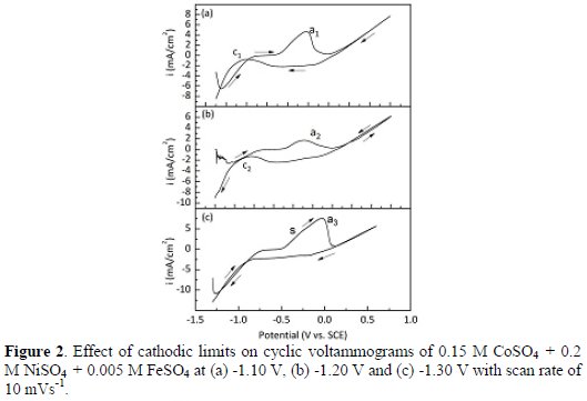
All cyclic voltammograms demonstrate almost a similar pattern as in Fig. 1. The results show that as the electrodeposition potentials were increased, the dissolution peaks shifted toward more positive potentials. In addition, the existence of shoulder at the higher potential, -1.30 V indicates that hydrogen dissolution has occurred.
The current-time transients were also recorded during the deposition process in order to control the stability of deposition, as suggested by Karpuz et al. [28].
Fig. 3 shows the current-time transients for the film grown at different deposition potentials for the first 30 seconds.
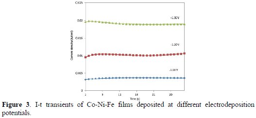
It is noticeable that the resulting current density between anode and cathode in the sulfate medium increased as the applied potentials increase towards negative direction. This indicates that the films formed on the surface electrodes are uniform as the current density values were almost stable for respective applied potentials.
FESEM micrographs of the Co-Ni-Fe alloy deposited at different potentials (Fig. 4) clearly show that the electrodeposition occurred uniformly regardless of applied potential values but larger particles were formed when higher electrodeposition potentials were applied.
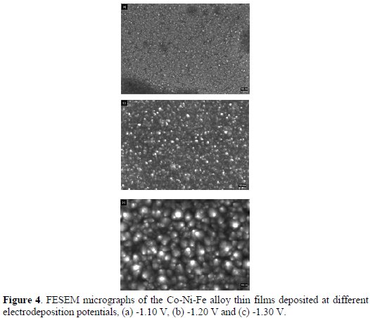
This is because when the electrodeposition potentials increase, the deposition kinetics will increase, leading to a rapid growth in particles size [29].
It is also suggested that the decreasing of iron content in the films leads to the increase in size of particles, especially in the case of short time electrodeposition [30]. The EDX for the alloy thin films obtained at -1.30 V show the existence of Co, Ni and Fe peaks (Fig. 5) confirming that Co-Ni-Fe alloy is present in the film.
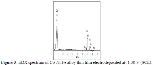
Fig. 6 shows the decrease of Co and Fe content of the alloy with the increase of electrodeposition potentials, while Ni content is otherwise.
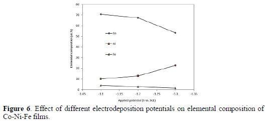
It can be concluded that the alloy grown in the respective potential range exhibits a kinetic behaviour known as anomalous codeposition where less noble metals are favorably deposited [31]. Although there is a slight decrease in Co and Fe content but increase in Ni content, the nature of anomalous codeposition is still followed where the composition for Co is higher than that of Ni but not for Fe, due to low concentration of iron precursor in the bath composition. Amongst explanations for anomalous codeposition are based on the assumption that, in the iron group metal, electrodeposition of the metal iron hydroxide ions, MOH+(M = Co, Ni, Fe), are the primary precursors competing with each other for surface sites at the electrode [32]. Inhibition of the electrodeposition of more noble element is assumed to result from preferential coverage according to the order where FeOH > CoOH > NiOH, due to the dissimilarities in kinetics [33]. Therefore, the anomalous phenomenon occurred during the fabrication of Co-Ni-Fe films was further analyzed using the selectivity ratio approach. The proposed method is defined as atomic percentage ratio of less noble element over more noble element in deposit over the molar ratio of their salts in the electrolyte, (am/an) / (Cm /Cn) where a is the at.%, C is the molar concentration, m and n are less and more noble elements, respectively [34]. Fig. 7 shows the preferential order of anomalous codeposition as follows, Co/Ni > Fe/Ni > Fe/Co. The significant finding by this approach is that the extent of anomalous codeposition for Co-Ni-Fe films is larger at deposition potentials > -1.30 V.
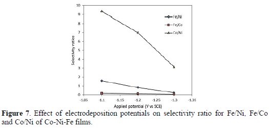
Fig. 8 illustrates the X-ray diffractograms of Co-Ni-Fe film electrodeposited on ITO substrate at different applied potentials.
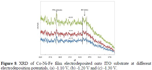
It shows the presence of face- centered cubic (fcc) solid solution. The increase in intensity of the fcc diffraction peak as the applied potentials were increased indicates that nickel content was increased. The existence of only fcc crystal structure is strongly believed due to less Fe content in the films [35], as shown in Fig. 6.
It has been also demonstrated that low Fe will lower Fe/Co ratio (Fig. 7) thus decreases phases with body centered cubic (bcc) crystal structure in the Co-Ni- Fe deposit. The broader peak of the fcc alloy demonstrated in Fig. 8 reflects the amorphous character of the thin film alloys [14]. In this study, it was revealed that the use of ITO as the substrate led to the formation of amorphous phase, which agreed well with the findings of other workers [36, 37]. However, the use of copper substrate for example, can yield crystalline phase of the deposits [38, 39]. The amorphous phase is suitable for super capacitor application, as proton can easily permeate through the bulk of the electrode materials where the whole electrode can be utilized for energy storage [40].
Typical room temperature hysteresis curves of the alloy are shown in Fig. 9 with magnetic field up to 12 kOe.
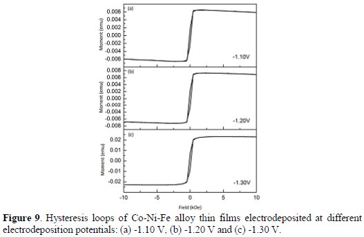
The magnetic hysteresis curves revealed the existence of ferromagnetic phases. The extended analysis results for other properties obtained from the hysteresis curves, i.e., Hc and Ms are shown in Fig. 10.
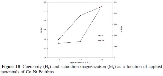
It can be seen that the Ms increased from approximately 653 A/m to 2307 A/m as the electrodeposition potentials were increased from -1.10 V to -1.30 V. The Hc values changed slightly between 100 Oe and 118 Oe from -1.10 V to a more negative potential, -1.30 V. Based on the previous discussion on the composition of the alloy film (Fig. 6), the increase in Ms may be due to the decrease in Fe content where Fe has lower Ms value than Ni [41]. The change in Hc values might be due to the effect of higher content of Co which led to a slight increase in Hc. Kim et al. [42] reported that Hc from sulfate medium was not depending on iron content in the deposit.
Fig. 11 shows the variation of alloy composition, Ms and Hc with the film thickness for films grown within certain potential ranges.
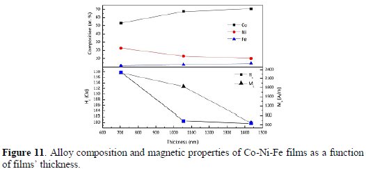
In some literatures [9, 43] the variation of Hc is explained using 4/3 law or better known as Neel's relation [44], i.e., Hc = Atn where A is a constant, t is the film thickness, and n = -4/3. The relation suggests that the changes that occur in the coercive force as the thickness of the magnetic layer decreases to a point where the domain wall thickness are comparable with the film thickness. In our work, we found that the Hc decreased with thickness of Co-Ni-Fe films which seems to follow the Neel's relation. Whereas Ms values were varied in agreement with the variation of alloy composition.
Conclusions
Ternary alloy of Co-Ni-Fe thin film was successfully co-deposited on ITO substrate by potentiostatic electrodeposition method without any additive. The CV of electrolyte containing metal ions of Co, Niand Fedo not differ significantly from single metal ion voltammograms. The presence of dual cathodic regions after Fe2+ was added, indicates the reduction of iron ion was more dominant compared to cobalt ion and nickel ion. The broad ranges of cathodic potential region indicate that diffusion-limited deposition takes place in the redox reaction. Both results from the current-time transients and morphological analyses confirmed the uniformity of the thin films structure and contained larger particles as applied potentials increase. The behavior of anomalous codeposition of Co, Ni and Fe was as follows, where Co/Ni was the most anomalous, Fe/Ni was intermediate and Fe/Co was the least anomalous. The dominant phase of the Co-Ni-Fe thin film was amorphous with the presence of crystallized phase of fcc structure. Both Hc and Ms values were increased as the applied potentials increase leading to high Co content and lowering Fe content, respectively. However, Neel's law revealed otherwise where Hc decreased with the increase of Co-Ni-Fe thin film thickness.
References
1. Schwarzacher W, Lashmore DS. IEEE Trans Magn. 1996;32:3133. [ Links ]
2. Daud AR, Budi S, Radiman S. Sains Malays. 2011;40:1019. [ Links ]
3. Budi S, Daud AR, Radiman S, et al. Appl Surf Sci. 2010;257:1027. [ Links ]
4. Pandya DK, Kumar Y, Kashyap SC, et al. Int J Nanosci. 2006;5:605. [ Links ]
5. Rasmussen FE, Ravnkilde JT, Tang PT, et al. Sensor Actuat A-Phys. 2001;92:242. [ Links ]
6. Osaka T, Takai M, Hayashi K, et al. Nature. 1998;392:796. [ Links ]
7. Liao SH. Thin film core of Co-Fe-B alloy. US Patent 5,168,410.1992. [ Links ]
8. Andricacos PC, Robertson N. IBM J Res Dev. 1998;42:671. [ Links ]
9. Liu X, Zangari G, Shen L. J Appl Phys. 2000;87:5410. [ Links ]
10. Nam H-S, Yokoshima T, Nakanishi T, et al. Thin Solid Films. 2001;384:288. [ Links ]
11. Osaka T, Sawaguchi T, Mizutani F, et al. J Electrochem Soc. 1999;146:3295. [ Links ]
12. Wen M, Qiu-Yan L, Ya-Fen W, et al. Colloids Surf A. 2008;318:238. [ Links ]
13. Rhen FMF,McCloskey P, O'Donnell T, et al. J Magn Magn Mater. 2008;320:819. [ Links ]
14. Sziraki L, Kuzmann E, El-Sharif M, et al. Appl Surf Sci. 2010;256:7713. [ Links ]
15. Gurrappa I, Binder L. Sci Technol Adv Mat. 2008;9:1. [ Links ]
16. Azizi A, Khelladi MR, Beniaiche A, et al. Int J Nanosci. 2013;12:1250038. [ Links ]
17. Maksimovic VM, Pavlovic LJ, Pavlovic MG, et al. J. Appl. Electrochem. 2009;39:2545. [ Links ]
18. Chen Y, Wang QP, Cai C, et al. Thin Solid Films. 2012;520:3553. [ Links ]
19. Nikolic ND, Popov KI, Pavlovic LJ, et al. Surf Coat Technol. 2006;201:560. [ Links ]
20. Popov KI, Pavlovic MG, Maksimovic MD. J Appl Electrochem. 1982;12:525. [ Links ]
21. Shao S, Zhang G, Zhou H, et al. Solid State Sci. 2007;9:725. [ Links ]
22. Gomez E, Labarta A, Llorente A, et al. J Electroanal Chem. 2001;517:63. [ Links ]
23. Afshar A, Dolati AG, Ghorbani M. Mater Chem Phys. 2003;77:352. [ Links ]
24. Grujicic D, Pesic B. Electrochim Acta. 2004;49:4719. [ Links ]
25. Palomar-Pardave M, Scharifker BR, Arce EM, et al. Electrochim Acta.2005;50:4736. [ Links ]
26. Abd El Rehim SS, Khaled K, Abulkibash AMS, et al. Trans Inst Met Finish. 2000;78:41. [ Links ]
27. Bockris JOM, Conway BE, White RE. Modern aspects of electrochemistry. Springer; 1990. [ Links ]
28. Karpuz A, Kockar H, Alper M. Eur Phys J - Appl Phys. 2009;48:30504. [ Links ]
29. Kwong WL, Qiu H, Nakaruk A, et al. Energy Procedia. 2013;34:617. [ Links ]
30. Abdel-Karim R, Waheed AF. Nanocoatings. 2013. [ Links ]
31. Zhang Z, Leng WH, Shao HB, et al. J Electroanal Chem. 2001;516:127. [ Links ]
32. Sasaki KY, Talbot JB. J Electrochem Soc. 2000;147:189. [ Links ]
33. Larson RS. J Electrochem Soc. 2007;154:D427. [ Links ]
34. Phan NH, Schwartz M, Nobe K. J Appl Electrochem. 1991;21:672. [ Links ]
35. Chisholm C, Kuzmann E, El-Sharif M, et al. Appl Surf Sci. 2007;253:4348. [ Links ]
36. Jian-Feng H, Xiao-Bo M, Li-Yun C, et al. Mater Lett. 2007;61:3920. [ Links ]
37. Dubal DP, Kim WB, Lokhande CD. J Alloys Comp. 2011;509:10050. [ Links ]
38. Karaagac O, Kockar H, Alper M. J Optoelectron Adv Mater. 2013;15:1412. [ Links ]
39. Gong J, Riemer S, Morrone A, at al. J. Electrochem Soc. 2012;159:D447. [ Links ]
40. Adekunle A, Ozoemena K, Agboola B. J Solid State Electrochem. 2013;17:1311. [ Links ]
41. Su X, Qiang C. Bull Mater Sci. 2012;35:183. [ Links ]
42. Kim D, Park DY, Yoo BY, et al. Electrochim Acta.2003;48:819. [ Links ]
43. Liu X, Evans P, Zangari G. IEEE Trans Magn. 2000;36:3479. [ Links ]
44. Neel L. J Phys Radium. 1956;17:250. [ Links ]
Acknowledgements
The authors would like to thank the Ministry of Higher Education of Malaysia and Universiti Kebangsaan Malaysia (UKM) for supporting this project under research grants UKM-OUP-2012-137, DIP-2012-32 and DIP-2014-022.
*Corresponding author. E-mail address: ismail.hnf@gmail.com
Received April 14, 2015; accepted 10 October 2016

