


Serviços Personalizados
Journal
Artigo
 Inglês (pdf)
 Artigo em XML
 Referências do artigo
 Enviar este artigo por email
Indicadores
-
 Citado por SciELO
 -
 Acessos
Links relacionados
-
 Similares em
SciELO
Similares em
SciELO
Compartilhar

 Permalink
Portugaliae Electrochimica Acta
versão impressa ISSN 0872-1904
Port. Electrochim. Acta vol.34 no.4 Coimbra jul. 2016
https://doi.org/10.4152/pea.201604257
New Development of Anodic Electro-catalyst for Chlor-alkali Industry
Muhammad S. Zafara,* , Muhammad Tausifb , Zia-ul-Haqc , Muhammad Ashrafqc and Sarfraz Hussainc
a Department of Chemical Engineering, University of Engineering and Technology (Faisalabad Campus) Lahore, Pakistan
b Department of Textile Engineering, University of Engineering and Technology (Faisalabad Campus) Lahore, Pakistan
c Department of Chemical Engineering, NFC Institute of Engineering & Fertilizer Research, Faisalabad, Pakistan
Abstract
Anodic electro catalysts are developed by using a titanium substrate coated with different compositions of mixed oxides, as it follows: ruthenium-titanium mixed oxides; ruthenium-titanium-tin mixed oxides; and ruthenium-titanium-iridium mixed oxides. The performance of electro catalysts was further evaluated by measuring coating thickness, studying coating morphology with microscope, identifying the presence of RuO2, TiO2, IrO2 and SnO2 in coating film, analyzing shape of individual crystal by XRD, performing accelerated life test and current efficiency test of the selected anode. The coating composition of 15% RuO2, 15% IrO2 and 70% TiO2 exhibited premium properties among the studied anodes.
Keywords: Electrode, XRD, DSA, Accelerated Life Test, Titanium..
Introduction
Electro-catalyst enables the electron transfer reactions at the electrode-electrolyte interface with substantial energy savings. The total energy consumption in the chlor-alkali process is proportional to the total cell voltage, including thermodynamic potential of anodic and cathodic reactions, electrode over potential, ohmic drop from the electrolyte, membrane and bubble effect, etc. [1]. The electrode upon which oxidation occurs in an electrochemical cell is called ''Anode''. The design and selection of the parameters of anodes have traditionally been associated to optimization of fixed and operating costs of the anode. Most of the materials used in anode fabrication are characteristically expensive. However, higher costs are justified by enhanced performance and reduced operational costs. An additional consideration in the selection of an appropriate anode is that it should be environment-friendly.
Historically, graphite anodes were commonly employed in brine electrolysis industry. The use of these anodes was abandoned due to the consumption of graphite anodes during the process. Moreover, the use of metal phosphides and metal disulfides as electro-catalysts in electrochemical cells, especially with alkaline electrolytes, was also a common practice [2-4].
Later on, the electro-catalysts based on platinum and nickel were developed, and the brine electrolysis industry switched over to the use of these Dimensionally Stable Anodes (DSA) with subsequent industrial applications. The combination of innovative techniques like energy-saving membrane cell technology and DSA has since become the most preferred choice in the design and construction of new chlor-alkali industry [1, 5, 6]. DSA have the following main advantages compared to those of previously used graphite anodes:
-lower power consumption;
-longer anode life;
-stability of electrodes during electrolysis;
-elimination of environmentally harmful materials;
-relatively consistent and stable cell room operation;
-reduction in labor.
Compact and crack-free coatings can be used as protective inner layer for the fabrication of DSA [7]. Hence, the DSAs are coated with expensive coating materials. The formulation of coating solution varies in each case, while coating process parameters remain the same. Main types of DSA coatings used in electrochemical industries are:
-ruthenium oxide based coating;
-iridium oxide based coatings;
-mixed ruthenium-iridium oxides coatings;
-platinum-iridium coatings;
-ternary system of coatings.
About 3 tons of ruthenium per year (12% of the annual production of ruthenium) are used for the fabrication of anodic electro-catalytic coatings [8]. Ruthenium based electro catalytic anodes find applications in water electrolysis, electroorganic synthesis and electrochemical oxidation. [9-11]. Such types of anodes are used in caustic-chlorine cells, chlorate cells, sea water electrolysis and similar applications. Different coating schemes are proposed and analyzed in the past, however, Henri Bernard Beer, in his patents, suggests the use of a combination of oxides, as they exhibit low cell voltage and have a long life. He coated the titanium substrates with mixed crystals of valve metaloxides and platinum group metal oxides by thermal decomposition techniques, and applied this in DeNora mercury cells; they exhibited low cell voltage and a long life [12-14]. Hence, mixed coating compositions are studied in this research.
Technical innovation to improve the energy-efficiency and resource-efficiency in the chlor-alkali industry has become a critical issue in view of the current energy and environmental challenges being faced and the increasing shortages in the primary resources [15]. An attempt was made to reduce the electrode potential by about 100 mV (about 3-4% energy saving) and to reduce the ruthenium content [9-11].
The work presented in this paper aims to develop new anodic electro catalysts by using a titanium substrate, determine the optimum ruthenium oxide based electro catalytic coating composition, and subject the specimen to an optimized coating composition for current efficiency measurement to a pilot plant of 1.3 kg capacity of sodium chlorate per day.
Materials and methods
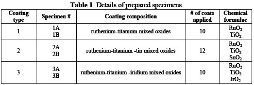
In this experimental work, different ruthenium oxide based coatings for DSA were prepared, followed by non-destructive testing (NDT) and electrochemical analysis to find out optimum coating composition. Both binary and ternary oxide systems were studied. Ruthenium-titanium mixed oxide coatings were investigated in binary systems (Type 1), whereas iridium-ruthenium and titanium di-oxide and ruthenium-titanium and stannic oxide coatings were investigated in ternary system (Type 2 and 3). Process parameters (chemical etching temperature and time, baking temperature and time, annealing temperature and time and loading of noble metals) for all types of coating compositions were kept fixed. The followed experimental design and the details of the prepared specimen are depicted in Table 1.
The performance of anodes was analyzed using Accelerated Life Test. In this technique, the test specimen of DSA was electrolyzed in a saturated brine solution (260∼290 g L-1 of NaCl) under constant current (operating current density 30 kA m-2) and terminal voltage. The brine solution was circulated by a sealed pump, in order to keep the composition of the solution uniform. The pH of the solution was maintained between 6∼7. The voltage across the working and reference electrodes was recorded until the voltage increased sharply and the test specimen broke down. In Accelerated Life Test, the cell voltage slowly decreases at first (due to the activation of the inner surface in the porous anode), then the voltage remains unchanged for a long period of time, and finally steeply decreases at the end of the specimen's service life. The specimen with the highest accelerated life time was further subjected to a Current Efficiency Measurement test.
Process description
The coating process of DSA is comprised of the following five stages, and the process flow chart is provided in Fig. 1.
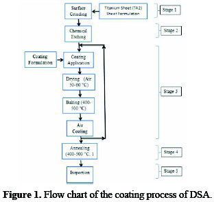
1) Preparation of titanium substrate; 2) Application of a coating solution to the substrate; 3) Baking of coated substrate; 4) Annealing of specimen; and 5) Inspection of coated anodes
Preparation of substrate
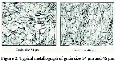
A specimen of titanium sheet (Chinese standard: TA2) with a grain size of 25∼55 μm was selected. The sheet was grounded with sand paper for the removal of foreign matter. For determination of the grain size, metallography of titanium sheet was performed with the aid of an optical metallurgical microscope. Typical micrographs, for 3B (having grain size of 54 μm) and 2B (having grain size of 46 μm) are shown in Fig. 2.
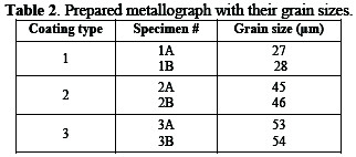
The ground specimen was etched for three hours with oxalic acid (10% w/w) at 80 °C. The results of morphology for different specimens are depicted in Table 2.
Application of a coating solution to the substrate
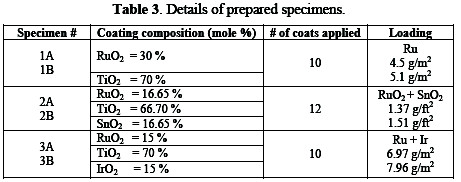
The surface of specimens was painted with a coating solution; formulations are given in Table 3.
Baking of painted substrate
The painted specimens were dried with hot air at 50∼60 °C. The suitable thermal sintering temperature for the fabrication of anodic coatings is between 400-550 °C. The dried specimens were baked in the presence of excess air at 450 °C in a furnace for 10 minutes. Higher temperatures (> 550 °C) can result in the partial oxidation of the Ti substrate [16], which is likely to increase the ohmic resistance of the oxide film, due to the formation of an insulating TiOx interlayer. Thereafter, the specimens were cooled and painted again. The process of painting, drying, baking, and cooling was repeated until desired thickness of ruthenium metal was obtained.
Annealing
Finally, the specimens were heated at a temperature of 450 °C for one hour, and were gradually cooled down to ambient temperature. This process is called âAnnealingâ. It induces ductility, softens the material, relieves internal stresses, refines the structure by making it homogeneous, and improves the cold working properties. Details of prepared specimens are given in Table 3.
Inspection of coated anodes
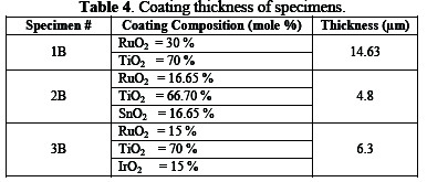
The inspection of anodes was carried out in order to determine coating quality, material identifications and performance of the anode. The coated specimens were inspected with optical metallurgical microscope for the verification of coating morphology and measurements of coating thickness (Table 4).
The coated specimens were also inspected for the identification of compounds\elements and for the study of the crystal structure with XRD.
Results
The results are tabulated, graphically reported and critically discussed as:
Coating morphology
Coating morphology can affect the electrode performance, such as the available active surface area, electrode deactivation due to the passivation [17], and also the gas bubble evolution behavior during the process [18]. Typical micrographs of different anodes are shown in Figs. 3 and 4.
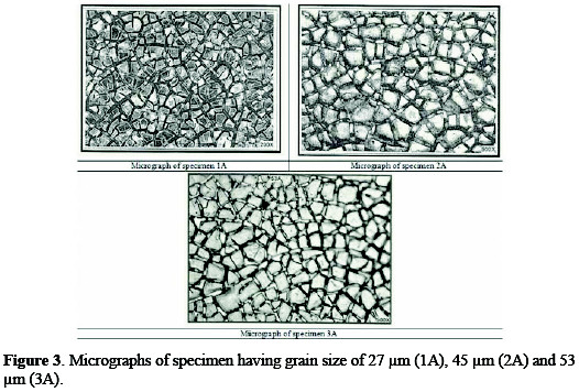
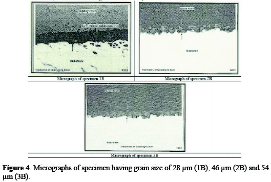
All the three micrographs show a characteristic micro-cracked surface. These cracks have occurred early in the coating, because solvent evaporated from the surface and left a gel of unreacted ruthenium, iridium, tin and titanium compounds. Further, as the coating was baked at higher temperatures, these cracks increased in size, because of the volume contraction of the gel [19]. The establishment of cracks caused the increase in surface area compared to that of the geometrical area. The increase in the surface area contributes to low chlorine discharge potential of these coatings and, hence, can provide a large number of catalytic sites for gas evolution, while minimizing concentration polarization.
Identification of elements and compounds
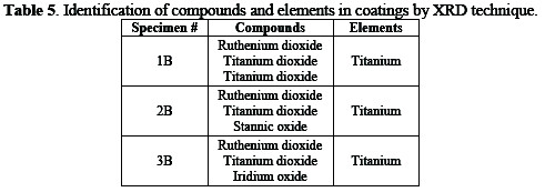
Different specimens were analyzed by X-ray diffractometer for the identification of elements and compounds in the coating solution, and for the study of the structure of the solid solution. XRD peaks of different specimens are shown in Fig. 5.
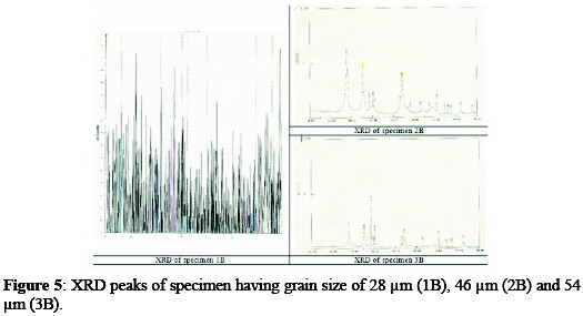
It is clear that the specimen 1B, possessing the larger peaks, has a high concentration of titanium on its surface.
The compounds and elements present in the coatings of the three specimens identified by the XRD technique are given in Table 5.
Performance of the anode
Accelerated Life Test and Current Efficiency Measurement techniques were used to evaluate the performance of anodes.
Accelerated life test
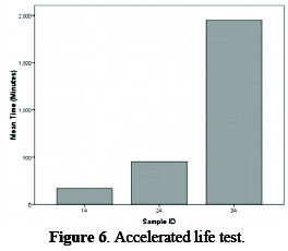
The continuous tests stimulating industrial conditions and employing an operating current density of 3 kA m-2 would certainly provide reliable data on anode durability, but would require 2-3 years per test. Keeping this fact in view, the procedure was modified during the experimentation by operating the test anode at a high current density (30 kA m-2) at room temperature, in dilute brine (30 g L-1). The brine is circulated by a sealed pump, in order to keep the composition of solution uniform, and the pH of the solution is also maintained between 6∼7. These conditions give a potential voltage, i.e., greater than the critical value of 1.4 V, where corrosion of coating occurs within a few hours. The result of this test is shown in Fig. 6, which depicts that specimen #3A has the maximum life among the studied specimens.
Current efficiency measurement
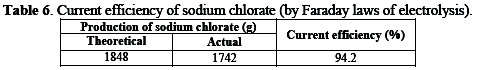
The fabricated anode was installed in a pilot plant of sodium chlorate with capacity of 1.3 kg per day. The plant was operated at the same current density as in actual operation (2.2 kA m-2, 85 °C). After operating the plant for 34 hours, the current efficiency was found to be 94.2% (Table 6).
Conclusions
Ruthenium oxide based coatings on titanium are known to produce dimensionally stable anodes. The effect of coating types, number of coats and coating composition on the accelerated life of titanium anodes was experimentally studied. It was concluded that a ternary oxide system having iridium-ruthenium and titanium di-oxide coating, with the coating composition of 15% RuO2, 70% TiO2 and 15% IrO2, exhibited the longest accelerated life among studied specimens, and showed a current efficiency of 94.2%. Hence, the life of titanium anode could be prolonged by employing a ternary oxide system having a moderate coating thickness of 6.3 μm to inhibit corrosion. It is likely to have economical as well as environmental benefits, due to the slow depletion of the anodes which are manufactured from finite natural resources.
References
1. Trasatti S. Electrochim Acta, 1991;36:225. [ Links ]
2. Mund K, Schulte R. Electro-catalyst and process of manufacture; 1976. Google Patents. [ Links ]
3. Larson TL, Method of producing a fuel cell electrode containing a nickel-phosphorous alloy as the catalyst. 1968. Google Patents. [ Links ]
4. Hills B. Electrode comprising non-noble metal disulfides or phosphides and electrochemical cell utilizing SAME. 1971, Google Patents. [ Links ]
5. Beer HB. J Electrochem Soc. 1980;127:303C. [ Links ]
6. Beer HB. in British Patent1965: British. [ Links ]
7. Chen R. et al. Chem Mater. 2010;22:6215. [ Links ]
8. Zhou H-C, Long JR, Yaghi OM. Chem Rev. 2012;112:673. [ Links ]
9. Kim K-W, et al. Electrochim Acta. 2005;50:4356. [ Links ]
10. Chiang L-C, Chang J-E, Wen T-C. Water Research. 1995;29:671. [ Links ]
11. Reichert E, et al. Phys Chem Chem Phys. 2012;14:5214. [ Links ]
12. Aromaa J, Forsen O. Electrochim Acta. 2006;51:6104. [ Links ]
13. Cronin B. Int J Technol Manag. 1989;4:411. [ Links ]
14. O'Brien TF, Bommaraju TV, Hine F., History of the Chlor-Alkali Industry. Handbook of Chlor-Alkali Technology: Volume I: Fundamentals. 2005. pp.17-36. [ Links ]
15. Ostertag K, Sartorius C, Espinoza LT. Chemie Ing Technik. 2010;82:1893. [ Links ]
16. Martelli G, Ornelas R, Faita G. Electrochim acta. 1994;39:1551. [ Links ]
17. Chen R, et al. Phys Chem Chem Phys. 2012;14:7392. [ Links ]
18. Chen R, et al. Electrochem Comm. 2012;22:16. [ Links ]
19. Kozuka H, et al. J Sol-Gel Sci Technol. 2000;19:205. [ Links ]
*Corresponding author. E-mail address: shahzadzafar2013@gmail.com
Received June 12, 2015; accepted July 30, 2016

