


Serviços Personalizados
Journal
Artigo
 Inglês (pdf)
 Artigo em XML
 Referências do artigo
 Enviar este artigo por email
Indicadores
-
 Citado por SciELO
 -
 Acessos
Links relacionados
-
 Similares em
SciELO
Similares em
SciELO
Compartilhar

 Permalink
Portugaliae Electrochimica Acta
versão impressa ISSN 0872-1904
Port. Electrochim. Acta vol.33 no.1 Coimbra jan. 2015
https://doi.org/10.4152/pea.201501023
Nile Blue and Nickel Organometallic Dyes Applied in Dye-sensitized Solar Cells
Elvira Siamia , Reza E. Sabzib,c,* , Fereshteh Rasoulib and Farshad Kheirid
a Department of Chemistry, Faculty of Science, Payame Noor Urmia University, Urmia, I.R. Iran
b Department of Chemistry, Faculty of Science, Urmia University, Urmia, I.R. Iran
c Institute of Biotechnology, Urmia University, Urmia, I.R. Iran
d Department of Chemical Engineering, Urmia University of Technology, Urmia, I.R. Iran
Abstract
Solar cells (Gratzel cells) have been highly regarded due to their extremely efficient and low-cost process of converting sun light into electricity. In this work screen printed electrodes were fabricated by spraying organic and organometallic dyes on glass and flexible aluminum foil. These solar cells were prepared based on three dyes, namely nickel Di thiocyanato bis(triphenyl phosphine), nickel Dimethylglyoxime and Nile blue, and the performance of these dye-sensitized solar cells (DSSC) has been experimentally evaluated. The solar cells were fabricated using thin TiO2 films; these films were characterized by FTIR. The dyes were characterized using UV-Vis and typical J-V and P-V curves of the cells. The best performance was obtained for the mixture of nickel Dithiocyanatobis (triphenyl phosphine) and Nile blue with an open circuit voltage (Voc) of 976 mV using an incident irradiation of 100 mW cm-2 at 25 °C.
Keywords: Nile blue, Nickel Dimethylglyoxime, Solar Cell, Dye sensitized.
Introduction
Due to the increasing demand for energy in the recent years, it is one of the major challenges of scientists to achieve carbon free renewable sources of energy for this century [1-4]. Among the renewable energies, solar energy is one of the most acceptable sources to respond the energy demand in the future [5]. Dye- sensitized solar cells (DSSCs) have attracted much attention due to their high efficiency and low cost solar energy conversion [6-8]. Unlike previous generations of PV devices based on solid semiconductor materials, a conventional configuration of the dye sensitized solar cell is a combination of solid and liquid phases. Electricity is produced on the photo electrode, which consists of porous titanium dioxide films sensitized with a thin layer of light- absorbing dye and a redox couple electrolyte [9-15].
Dye-sensitized solar cells on flexible substrates coated with indium tin oxide on polyethylene terephthalate or metal foil can substitute rigid glass substrates. Flexible DSSCs have many advantages such as low cost production, and their extensive use as a breakthrough in DSSC may be considered in commercial applications [16-17].
One of the main components of a dye-sensitized solar cell is a semiconductor which typically can be constructed by several wet chemical methods such as casting, doctor blading and various physical methods including sputtering and chemical vapor deposition [18-20]. Screen printing method is used to achieve the precise control over composition, porosity and thickness of the films at a low scale. Screen printing is inexpensive and fast and provides the deposition of dye films over large areas [20].
Dye is a basic component of dye-sensitized solar cells because of its central role in solar radiation absorption and electron injection into the oxide layer in conduction band [21]. To produce a photocurrent, the energy of the excited-state of the dye should be higher than the energy of the excited conduction band edge [22].
Choosing a suitable electrolyte is an important factor in increasing the efficiency of the cell. The oxidation process of the dye is reversible and the oxidized dye can be reduced again within the rate constant (Kb). Therefore, the electron transfer rate from the external circuit to the electrolyte must be faster than the dye regeneration [23-24]. Liquid electrolytes are often used in the dye-sensitized solar cells. To overcome the problems of liquid electrolytes (such as swings and leakage), solid and quasi-solid electrolytes are applied.
Unlike quasi-solid-state gel polymer electrolytes [25-26], in solid electrolytes, for example, sodium iodide crystallization, there are some problems due to the absence of solvent, and a low ionic conductivity occurs that reduces the efficiency and stability of the cell.
Gelation of the liquid electrolytes reduces the potential volatility in case of a solvent leak under thermal stress. In these systems, charge transfer occurs by molecular diffusion [27-28].
In this work, we focus on designing and constructing two screen printed electrodes which were made by spraying on glass and flexible aluminum foil; a conductive glass photo-anode electrode and aluminum foil electrode were used as counter electrodes. Then, the cell was optimized to achieve high output power and was exposed to light. In addition, to overcome the problem of using liquid electrolyte, a semi-solid-state gel electrolyte was used. Organic and organometallic dyes were used to sensitize the solar cell.
Experimental
Chemicals and materials
Conductive glass, high purity graphite powder, aluminum foil and TiO2, poly vinyl chloride (PVC), tetrahydrofuran (THF), nile blue (C20H20ClN3O), dithiocyanatobis (triphenyl phosphine) nickel(II) (Ni(NSCN)2(PPh3)2, nickel dimethylglyoxime (Ni(DMG)2) (mentioned Ni complex was synthesized), Agar, I2 and KI were purchased from Merck and used without further purification. All other chemicals were of analytical grade and were used without further purification.
Synthesis of dye complexes
Nickel dimethylglyoxime
We have dissolved 0.77 g Ni(DMG)2 in 50 mL distilled water; and added a small amount of ethanol and 0.11 g of dimethylglyoxime. A solution of 0.2 g NaOH in 5 mL distilled water was prepared. Ni(DMG)2 solution was immediately mixed with NaOH solution in a 100 mL beaker. After the addition is completed, the solution was stirred for 30 minutes at room temperature. The product has been separated by filtration, washed with distilled water and the material allowed to air dry. The products are shown in Fig. 1.
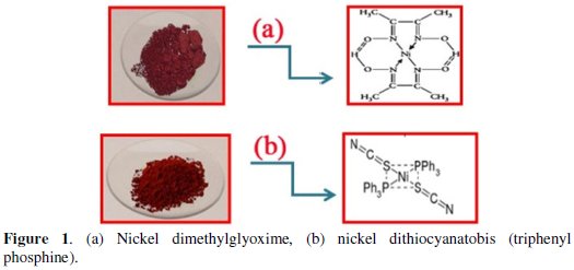
Dithiocyanatobis (triphenyl phosphine) nickel (II)
At first, 2.4 g of (Ni(NSCN)2(PPh3)2 and 3 g of finely powdered potassium thiocyanate were placed in a 200 mL beaker, and 150 mL 1-butanol were added to it. The resulting solution was refluxed for 2 hours under hood. After cooling, it was filtered using a Buchner funnel. The filtrate was heated to boil again and then it was added to a boiling solution of 5.3 g triphenyl phosphine in 50 mL 1butanol. The red particles precipitated and slowly cooled and were then filtered with a Buchner funnel. The product was washed with 1-butanol and then sealed under a beaker inside the hood for a week to dry.
Fourier Transform Infrared Spectroscopy (FT-IR)
The FT-IR spectra of the dyes were obtained from powdered dye samples pressed with potassium bromide at 1:100 (sample: Kbr) ratio with a hydraulic press (NEXUSE 670/USA). To obtain FT-IR spectra, the discs were scanned in the range of 500-4000 cm-1.
UV-VIS Spectroscopy
A WPA Biowave (II) UV-Vis spectrophotometer was employed for absorbance measurements. The UV-Vis spectra of the dyes were obtained from the mixture solution (1% v/v) in the range of 250-700 nm.
Preparation of dye solar cell electrodes
Photo-anode electrode
Photo-anode (Fig. 2a) consists of two composite layers.
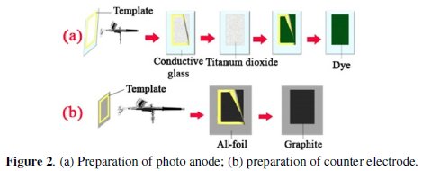
The first layer consists of titanium dioxide and polyvinyl chloride and the second layer is a composite of dye and polyvinyl chloride. At first TiO2 (0.024 g, 60%) was placed in a 5 mL beaker containing THF. The resulting slurry was mixed using ultrasonic. Then PVC (0.016 g, 40%) was added to the solution. The resulting solution was vigorously stirred. To prepare separate solutions of C20H20ClN3O, Ni(NSCN)2(PPh3)2 and Ni(DMG)2, 0/036 g (90%) of each of dyes were weighed and THF was added to make up 5 mL in the beaker. The resulting solution was mixed by ultrasonic mixer and then PVC (0.0004 g, 10%) was added. For preparing the used dye solutions, 0.04 M Ni(NSCN)2(PPh3)2, 0.03 M C20H20ClN3O were prepared in THF.
The conductive glass was fabricated according to previous reports [29-30]. For this purpose the solution was prepared by dissolving 4 g of Tin chloride (SnCl4.5H2O) in 4 mL methyl alcohol. Tin dioxide thin films were deposited on glass substrate using spray pyrolysis [29-30] technique at 580-660 °C substrate temperatures; the conductivity of the glass was 5 (Ω.cm)-1. The glass surface was cleaned by sequential washing with acetone and rinsed thoroughly with distilled water. After preparing the solution, TiO2 and PVC solutions were first sprayed on the surface of the conductive glass (cell area was equal to 4 cm2). For sintering, photo anode was heated in the oven at 500 °C for 15 minutes. Sintering removed the binder and solvent to create an electronically connected electron-conducting network. Then dye and PVC solutions were sprayed on the surface of titanium dioxide. In order to evaporate the solvent, the electrodes were heated at 150 °C for 10 minutes.
Counter electrode
In this part, an aluminum foil was used as substrate. Graphite (92%, prepared in THF) and PVC (8%) solutions were sprayed on the surface of aluminum foil and were allowed to evaporate at ambient temperature (25 °C) for 8 minutes (Fig. 2b).
Electrolyte preparation
The iodide/triiodide couple (0.588 mM potassium iodide, 0.096 mM iodine) was prepared in an ethylene glycol solvent and distilled water solution (water/organic ratios 30 to 70 wt%). Agar solution was prepared by dissolving agar in distilled water. Agar is insoluble in cold water but if dissolved in boiling water first and then cooled to 35 to 40 °C or less, it forms a gel. Then iodide/triiodide solution was added to the agar gel.
Cell assembly
In this step, the photoanode electrode was pressed on the top of the counter electrode with the help of two spring clips and an electrolyte layer was applied between the photoanode and the counter electrode, then the cell was fixed with epoxy resin.
Results and discussion
Nickel dithiocyanatobis (triphenyl phosphine) FTIR
The FTIR spectrum of reactive nickel dithiocyanatobis (triphenyl phosphine) is depicted in Fig. 3a.
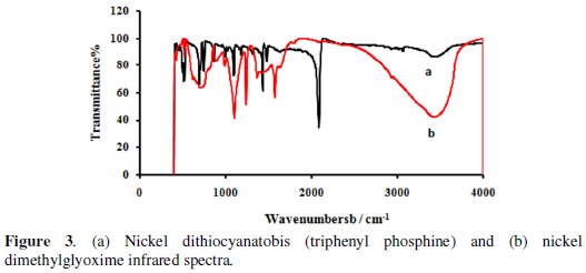
The peak at 2082 cm-1 corresponds to the stretching vibrations of -N=C=S group in the dye. The bending of PH in phosphines group exhibits the peak at 1090 cm-1 (Fig. 3a).
Nickel dimethylglyoxime FTIR
The infrared spectra of the nickel dimethylglyoxime exhibited absorption bands at 1566, 1099 and 682 cm-1 which are attributed to ν(C=N), ν(N-O) and ν(C=NO), respectively. There is a broad absorption band around 3200 cm-1 superimposed with a number of weak side bands which can be attributed to the N-O-H stretching mode (Fig. 3b).
Dye absorption spectra and the effect of titanium dioxide on the dye absorption spectra
To produce a photocurrent density, the energy of the dye excited-state necessarily must be higher than the conduction band edge. High quantum efficiency for injection is achieved when the dye LUMO is both energetically matched and reasonably strongly coupled with the underlying semiconductor [31-32]. In the presence of pure solvent, dye cation lifetime is about several milliseconds; however, in the presence of solvent systems such as iodine / triiodide, this amount is reduced to micro-seconds [33]. Fig. 4a, 4b and 4c show the absorption spectra in the region from 250 to 700 nm, 614 and 286 respectively, for the three diluted solutions (nickel dithiocyanatobis (triphenyl phosphine) (Fig. 4a), nickel dimethylglyoxime (Fig. 4b) and nile blue (Fig. 4c) ) in THF.
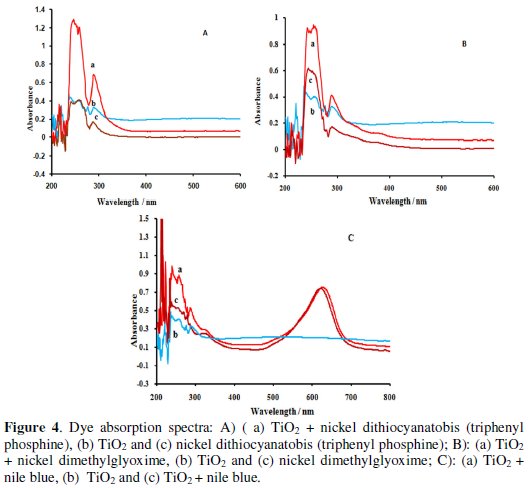
Nickel dithiocyanatobis (triphenyl phosphine) and nile blue mixture cover a greater range of the ultraviolet region. To achieve high quantum yields of the excited state electron transfer process, ideally the dye needs to be in intimate contact with the semiconductor surface [13, 23, 34]. The hydroxyl, amine and cyanine groups of the dye serve as grafting agents for the oxide surface of the TiO2 films [31-32]. We also measured the absorption spectra for free dye molecules. The absorption spectrum of dyes anchored on TiO2 (dispersed in THF with sonication) showed broadened and red-shifted absorption peaks due to their chemical interaction with TiO2 surfaces. In order to make solar cells efficient, rapid charge injection and transportation are required in addition to intense visible light absorption (Figs. 4a - 4c).
Characteristics of the electrolyte
Replacement of the liquid electrolyte by a solid-state analog (ionic solid or conducting polymer) increases stability like liquid electrolytes; a quasi-solid state polymer gel electrolyte [35] has high ionic conductivity and also suppresses the solvent leakage, thus showing good stability. Recent researches have focused on using a solid or gel as an acceptor [36]. In this research Agar was used for the first time in the preparation of a gel electrolyte. Agar consists of a mixture of agarose and agaropectin. This mixture can be used to make an agar gel, a translucent or transparent jelly like substance [37]. Due to the presence of agarose in agar, there are many pores, which help quick and easy electron transfer [38]. Agaropectin is a polysaccharide with smaller molecules and lower molecular weight. Agaropectin is a mixture of sulphated galactosyl which depends on the source from which it is obtained [39-40].
Due to numerous hydroxyl groups in the structure of Agar, it is assumed to be a desirable polymer matrix for forming cross-linking networks with other components in the polymer.
Characterization of the dye solar cell performance
Current-voltage (IV) curves are important tools to define characteristics of DSCs in general. I = f (V) curve explains the capability of the thermal radiant energy conversion in the DSCs. The prepared TiO2 films on conductive glass and aluminum foil substrates were examined as negative and positive electrodes, respectively (cell area is equal to 4 cm2). The performance of dyes in DSSCs was evaluated by short circuit current (Jsc), open circuit voltage (Voc), current density at maximum power (JMP), maximum power voltage (VMP), maximum power (PM) and fill factor (FF) (Table 1).
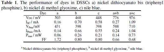
The photoelectrochemical parameters of the DSSCs sensitized with nickel dimethylglyoxime, nickel dithiocyanatobis (triphenyl phosphine) and nile blue dyes are listed in Table 1. These parameters were obtained from Fig. 5.
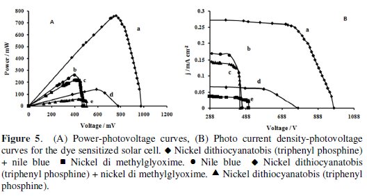
The photopower curves are shown in Fig. 5 A and the photocurrent-photovoltage (J- V) sample curves are presented in Fig. 5 B. When the light intensity increased, Jsc and Voc were also increased and ff depended on the maximum amount of radiation, electrolyte composition, electrolyte concentration, electrolyte viscosity and other parameters such as the cell design. The ff increased and decreased due to the cell voltage increases and the Ohmic losses in the conducting substrate, respectively. The open circuit voltage increases with increasing electron injection rate resulting in an increased chemical potential within the cell [41]. Nickel dithiocyanatobis (triphenyl phosphine) and nile blue dyes had the best performance parameters. Because the chemical adsorption of these dyes occurs due to the condensation of amine with the hydroxyl groups on the surface of TiO2, an optimal DSSC dye would have beneficial charge interception suppression of the nile blue while achieving a much higher molar absorptivity, especially in the red and near-infrared (NIR) regions.
Influence of temperature
Solar cells are sensitive to temperature. In a solar cell, the parameter most affected by an increase in temperature is the open-circuit voltage. Semiconductor band gap reduction due to increased temperature is the most important factor in decreasing the open-circuit voltage. Since the band gap energy decreases and more photons have enough energy to create e-h pairs, the short-circuit current increases slightly with temperature.
To investigate the effect of temperature on the cell (nile blue and Ni (NSCN) 2(PPh3)2), the open-circuit voltage was measured at different operating temperatures of 32, 40, 50 and 60 °C. The temperature did not affect the short circuit current. On the other hand, the operating temperature had an essential influence on the open-circuit voltage. It was observed that the voltage was significantly decreased at 50 °C and higher temperature leads to faster degradation (Fig. 6 A).
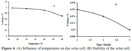
Stability
There are different potential sources of instability. The critical components for the lifetime are the dye, the electrolyte, and the redox couple. To investigate the stability of the cell, nile blue and Ni(NSCN)2(PPh3)2 cell was studied for 90 consecutive days and the results were plotted in Fig. 6 B. It was observed that there was not significant difference between the values obtained after 90 days and the values of the first day.
Conclusion
The purpose of the current study was to design a novel dye solar cell based on screen printed electrode technology. Desired dye-sensitized solar cell system based on TiO2, dithiocyanatobis (triphenyl phosphine) nickel, nile blue and nickel dimethyl glyoxime was constructed and characterized. Dithiocyanatobis (triphenyl phosphine) nickel (II) and nile blue dyes had the best performance parameters.
The effect of temperature on the cell fabricated using (nile blue and Ni(NSCN)2(PPh3)2) was determined and the open-circuit voltage was measured at different operating temperatures. The temperature did not affect the short circuit current and it remained unchanged. To investigate the stability of the cell, nile blue and Ni(NSCN)2(PPh3)2 cell was studied for 90 consecutive days; the experimental results showed that there was no difference between the results obtained for the first and 90th day. The most prominent features of this work include flatness, flexibility, printed electrodes and replacement of the liquid electrolyte with a polymer electrolyte.
References
1. Hirsch R L Energy Policy. 2008;36:881. [ Links ]
2. Lewis N S. MRS Bull. 2007;32:808. [ Links ]
3. Hughes J R. Oil Gas J. 2008;106:12. [ Links ]
4. Witze A. Nature. 2007;445:14. [ Links ]
5. Lewis N S, Nocera D G. Proc Natl Acad Sci USA. 2006;103:15729. [ Links ]
6. Jin L, Chen W, Chen D J. Serb Chem Soc. 2012;77:1223. [ Links ]
7. Imran M, Haider S, Ahmad K, et al. Arab. J. Chem. 2013. In press. [ Links ]
8. Regan B O, Gratzel M. Nature. 1991;353:737. [ Links ]
9. Hagfeldt A, Gratzel M. Acc Chem Res. 2000;33:269. [ Links ]
10. Hagen J, Schaffrath W, Otschik P, et al. Synth Met. 1997;89:215. [ Links ]
11. Halls J J M, Pickler K, Friend R H, et al. Nature. 1995;376:498. [ Links ]
12. Smestad G P, Graetzel M. J Chem Educ. 1998;75:752. [ Links ]
13. Graetzel M. J Photochem Photobiol: C Photochem Rev. 2003;4:145. [ Links ]
14. Spanggaard H, Kerebs F C. Sol Energy Matter Sol Cells. 2004;83:125. [ Links ]
15. Tulloch GE. J Photochem Photobio. 2004;164A:209. [ Links ]
16. Pichot F, Pitts J R, Gregg B A. Langmuir. 2000;16:5626. [ Links ]
17. Frisson L, Cheek G, Mertens R.et al. Commission Eur Commun Report Eur. 1984;1002. [ Links ]
18. Gratzel M. Inorg. Chem. 2005;44:6841. [ Links ]
19. Lee W G, Woo S I, Kim J C, et al. Thin Solid Films. 1994;237:105. [ Links ]
20. Suzuki S. Thin Solid Films. 1999;351:194. [ Links ]
21. Smestad G P, Graetzel M. J Chem Educ. 1998;75:752. [ Links ]
22. Durrant J R, Haque S A, Palomares E. Chem Commun. 2006;31:3279. [ Links ]
23. Macht B, Turrion M, Barkschat A, et al. Sol Energy Mater Sol Cells. 2002;73:163. [ Links ]
24. Wang P, Zakeeruddin S M, Moser J E, et al. Nature Mater. 2003;2:402. [ Links ]
25. Ragavendran K, Kalyani P, Veluchamy A, et al. Port Electrochim Acta. 2004;22:149. [ Links ]
26. Silva M M, Smith M J, Lightfoot P. Port Electrochim Acta. 1999;17:3. [ Links ]
27. Kubo W, Murakoshi K, Kitamura T, et al. J Phys Chem. 2001;105:12809. [ Links ]
28. Thorsmolle V K, Rothenberger G, Topgaard D, et al. Chem Phys Chem. 2011;12:145. [ Links ]
29. McMaster H A. US Patent Nº2. 1947;429,420. [ Links ]
30. Yuan Z, Li D, Liu Z, et al. J Alloys Comp. 2009;474:246. [ Links ]
31. Clifford J N, Palomares E, Nazeeruddin M K, et al. J Phys Chem C. 2007;111:6561. [ Links ]
32. Hara K, Horiguchi T, Kinoshita T, et al. Sol Energy Mater Sol Cells. 2000;64:115. [ Links ]
33. Ardo S, Meyer G J. Chem Soc Rev. 2009;38:115. [ Links ]
34. Thavasi V, Renugopalakrishnan V, Jose R, et al. Mat Sci Eng. 2009;63:8199. [ Links ]
35. Sharma JP, Sekhon SS. Port Electrochim Acta 2008;26: 493. [ Links ]
36. Araki C. J Chem Soc Japan, Pure Chem Seet. 1937;58:1338. [ Links ]
37. Araki C. Bull Chem Soc Japan. 1956;129:543. [ Links ]
38. Petrozza A, Groves C, Snaith H J. J Am Chem Soc. 2008;130:12912. [ Links ]
39. Snaith H J, Schmidt-Mende M, Gratzel M. Phys Rev. 2006;74:045306.
40. Usami A, Seki S, Mita Y, et al. Solar Energy Mater: Solar Cells 2009;93:840. [ Links ]
41. Saikia D, Han CC, Chen-Yang YW. J Power Sources. 2008;185:570. [ Links ]
*Corresponding author. E-mail address: rezasabzi@yahoo.com
Received 14 November 2014; accepted 2 February 2015

