


Serviços Personalizados
Journal
Artigo
 Inglês (pdf)
 Artigo em XML
 Referências do artigo
 Enviar este artigo por email
Indicadores
-
 Citado por SciELO
 -
 Acessos
Links relacionados
-
 Similares em
SciELO
Similares em
SciELO
Compartilhar

 Permalink
Portugaliae Electrochimica Acta
versão impressa ISSN 0872-1904
Port. Electrochim. Acta vol.31 no.6 Coimbra nov. 2013
https://doi.org/10.4152/pea.201306331
Comparison of Material Properties of LiCoO2 Doped with Sodium and Potassium
T. Kazda*, J. Vondrák , M. Sedlaríková, O. Cech
Department of Electrical and Electronic Technology, Faculty of Electrical Engineering and Communication, BUT, Technicka 10, 616 00 Brno, Czech Republic
Abstract
The aim of this study was to improve the properties of cathodic material for lithium-ion batteries based on LiCoO2. The solid phase reaction method was chosen as a manufacturing method of the doped base material. This method has already been tested for the production of basic material. Materials selected from the group of alkali metals were chosen as the doping elements. The main objective was to use these added elements for stabilizing the structure of the LiCoO2 material and for limiting the process of their degeneration.
Keywords: lithium ion batteries, cathode material, lithium cobalt oxide, sodium, potassium.
Introduction
Li-ion accumulators are (if we do not take the external structure into account) made up of three basic components: a cathode, an anode and an electrolyte. The anode and the cathode are formed by the so called intercalation substances. These substances are characterized by the ability to release and incorporate lithium ions in their structure, thereby these batteries differ from the conventional ones in which there is chemical conversion of the anode and cathode material. Metal oxides of the spinel and olivine layered structure are used as cathode materials [1-2]. Carbonaceous materials are used as anode ones. Currently the most used positive electrode material for lithium-ion cells is LiCoO2, being this material characterized by a layered structure, its voltage against lithium (3.9 V), and its capacity (155 mAh/g). The first commercial lithium-ion batteries made by Sony came on the market in 1991; LiCoO2 was used as a cathode material in these batteries. This type of structure means a number of disadvantages [1,3-5]. The main disadvantage of this structure is its collapsing during repeated intercalation and deintercalation of lithium ions from the structure, which results in decreasing the capacity of this material. Another problem of this material is its temperature instability: it leads to the release of oxygen from the structure at higher temperatures. This oxygen reacts with the organic solvents contained in the electrolyte and generates heat. Thermal stability of LiCoO2 is affected by the type, particle size and concentration of electro-lithium salts which strongly depend on the content of the electrolyte [2]. The research has been focused on covering the surface of LiCoO2 with an appropriate coating of metal oxides (Al2O3, ZrO2, MgO, SnO2) for solving this problem. This coating makes a barrier preventing the reaction between LiCoO2 and the electrolyte. The coating decreases the structural damage of LiCoO2 and improves its capacity during cycling [6]. A number of alternative materials was created in an effort to eliminate the disadvantages which are bound to the LiCoO2 material. An example of such a material may be LiNiO2: this material has a layered structure similar to LiCoO2 but its specific capacity is much higher (200 mAh/g) and its voltage against lithium is 3.55 V [1,2,7]. A great disadvantage of this material (LiNiO2) is its much lower thermal stability and greater exothermic decomposition than LiCoO2 at lower temperatures. The LiNi1-xCoxO2 material which combines the features of both previous ones is another alternative. Its specific capacity lies between 190 mAh/g and 220 mAh/g and its voltage against lithium is about 3.75 V [1,2,7]. One of the newest alternative materials is the LiFePO4 one this material is characterized by olivine structure which is much more thermally stable and does not degrade during intercalation and deintercalation of the lithium ions. Also, it is made of eco-friendly and cheap materials, which is an additional advantage. The specific capacity of LiFePO4 is ∼170 mAh/g and its voltage against lithium is 3.4 V [4,8]. Another existing alternative material is LiMn2O4. Its spinel structure gives it better stability than LiCoO2. This material is less toxic and its exothermic decomposition is lower due to the use of Mn. Its specific capacity is 148 mAh/g and its voltage against lithium is 4 V [2,4,9,10].
Experimental
Potassium and sodium were chosen as the doping materials. The method of doping LiCoO2 material with K and Na was chosen because the lithium compounds are volatile and sublimation occurs during the production of the basic material (during the annealing process). The addition of these alkalis should compensate the sublimation of lithium and result in better stability of the layered structure. The premise was that these elements would be incorporated between the layers of the structure and that they would prevent the collapse of the layered structure during the intercalation and deintercalation of lithium ions. The elements doped with sodium and potassium should therefore play the role of the pillars in the structure, stabilize this structure and facilitate the movement of lithium ions. The method of reaction in solid state was chosen for the production of this material. The basic materials used for the production were: Li2CO3 (Lithium carbonate -Sigma Aldrich 99%), CoCO3.xH2O (Cobalt (II) carbonate hydrate - Sigma Aldrich), Na2CO3 (Sodium carbonate - Sigma Aldrich 99.5 %) and K2CO3 (Potassium carbonate - Sigma Aldrich 99%). The three selected materials were mixed in the stoichiometric ratio in the first step. The volume of Li and Co was still the same but the content of K has been varied (1 %, 2.5 % and 5 %). This procedure was repeated in the next step and K was replaced with the same amount of Na (1 %, 2.5 % and 5 %). Mixing was done in a mixture of distilled water and ethyl alcohol in the ratio 2:1 and it was followed by drying at 90 °C for 12 h. The dried mixture was then milled in the ball mill, poured into a ceramic bowl and annealed for 30 h at 400 °C. The annealed material was subsequently grinded and pelleted; the resulting pellets were again annealed at 650 °C for 8 h. Grinding, pelleting and annealing were repeated in the next step of the process: this time at 950 °C for 8 h [11]. The mill was after each grinding thoroughly washed with water followed by alcohol and dried. The mill was filled with argon during grinding. The resulting material was grinded in the ball mill and then a mixture consisting of NMP (N-methyl-2-pyrrolidon, solvent), PVDF (polyvinylidenfluorid, binder) and carbon super P was created. The weight ratio of materials was: NMP 80%, Super P 10%, PVDF 10%. The mixture was subsequently spread on an Al foil, dried and pressed by the pressure of 3200 kg/cm2. A disk with a diameter of 18 mm was cut out of the coated aluminium foil and inserted into the electrochemical test (El-Cell© ECC-STD). The whole assembly was done in a glove box filled with argon atmosphere. Metal lithium was used as the counter electrode and the electrolyte was 1 M LiPF6 impregnated into the glass fibre separator, being the ratio EC:DMC 1:1 w/w.
Galvanostatic cycling was used for measuring; the potential window was set from 2.7 to 4.2V (versus lithium). Two cycles of charging and discharging have always been carried out during which the used charging and discharging currents were 0.5 C (calculated from the weight of the deposited material provided the capacity of the material is 120 mAh/g). The real value of the capacity of the sample has been deducted from these two cycles and then the sample was cycled five times by 0.5 C current. The rate of capability was measured for one selected sample; the sample was always charged by 0.1 C current and the discharge was carried out seven consecutive times by the currents 0.1 C, 0.2 C, 0.5 C, 1 C, 2 C, 5 C and 10 C.
Results and discussion
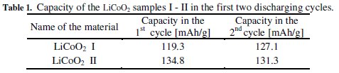
All produced samples of LiCoO2 + x%Na and LiCoO2 + x%K were compared with the samples of pure LiCoO2 produced in a similar way in three annealing bowls, and labelled I-II.
Almost all samples' capacities in the group of LiCoO2 + x%K materials were comparable to the samples of LiCoO2. LiCoO2 + 5%K material was used for comparison. It is similar in the group of LiCoO2 + x%Na materials: their capacities are similar to the capacities of LiCoO2 samples. LiCoO2 + 5%Na and LiCoO2 + 2.5%Na materials were used for comparison. The comparison of selected materials can be seen in Fig. 1.
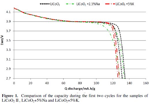
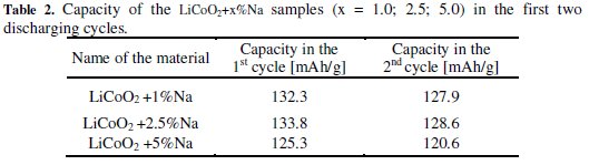
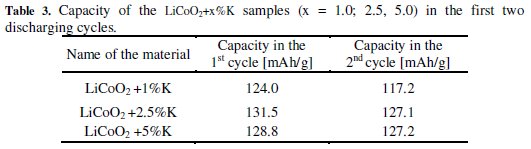
We can see from the results of the measurements that the groups of LiCoO2 + x%Na and LiCoO2 + x%K materials achieved during the first two cycles similar capacities as the basic material LiCoO2. The discharge curve was steeper in the case of the group of LiCoO2 + x%Na materials and these materials reached lower voltage much earlier. Also, the capacity difference between the first and second cycles was greater than from the basic material. These differences are evident from Fig. 1 and Tables 1, 2 and 3.
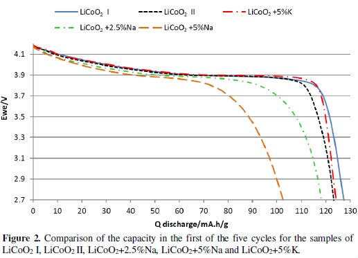
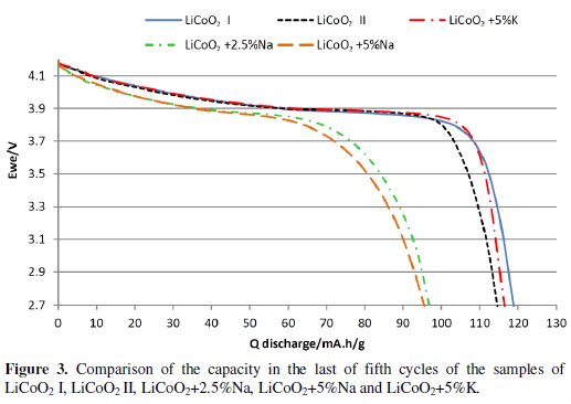
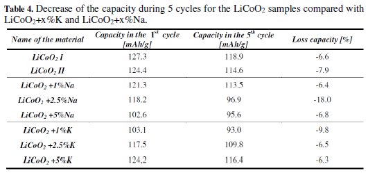
During the measuring of 5 charging / discharging cycles by the 0.5 C current it was found that materials from the group LiCoO2 + x%Na have a higher decline in capacity and overall lower capacity than the base material and also more rapid voltage drop than LiCoO2 material. Materials from the group LiCoO2 + x%K also showed lower capacity and higher drop of the capacity with the exception of the material LiCoO2 + x%K. This material had similar capacity as the base material and showed slightly lower capacity decrease than the base material. When compared with materials from the group LiCoO2 + x %Na and the base material in Fig. 2 and Fig. 3, and in Table 4, we can see that this material has much more gradual decrease in discharge voltage than the base material and the difference is even more evident with the increasing number of cycles.
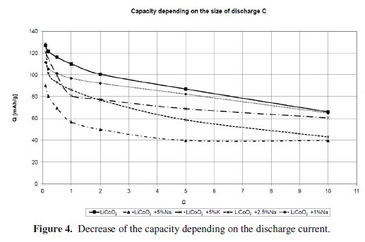
Then the measurement of the Rate Capability was done and it was found that none of the materials is able to achieve better results than the basic material LiCoO2 at a higher load vis. Fig. 4.
Conclusion
Both groups of the doped materials achieved similar capacities as the basic LiCoO2 material during the first two cycles. But the LiCoO2 + x%Na group showed steeper decrease of the discharging curve and of the capacity during cycling. It was discovered that the materials from the LiCoO2 + x%Na group were losing capacity faster and the decrease of the discharging curve was steeper during cycling than for the basic material. The materials from the LiCoO2 + x%K group showed lower capacity and their steeper decrease. The only exception was the LiCoO2 + x%K material which showed similar capacity as the pure LiCoO2 material and slightly lower capacity and voltage decrease during discharging. The positive effect of doping to stabilization of the structure will most likely begin to show up at a higher representation of the doping element. The atoms of potassium have slightly larger radius compared to sodium atoms which could help to improve the intercalation of Li during its inclusion. We will focus on the analysis of doping it with a higher proportion (up to 10% in our future work).
References
1. Ozawa K. Lithium ion rechargeable batteries. Wiley; 2009. [ Links ]
2. Linden D, Reddy TB. Handbook of batteries. McGraw-Hill; 2002. [ Links ]
3. Kezuka K, Hatazawa T, Nakajima K. J Power Sources. 2001;97-98:755. [ Links ]
4. Ohzuku T, Brodd RJ. J Power Sources. 2007;174:449. [ Links ]
5. Van Schalkwijk WA, Scrosati B. Advances in lithium-ion batteries. Kluwer Academic/Plenum Publishers; 2002. [ Links ]
6. Pu X, Yin L, Yu C. J Nanopart Res. 2012;14:1-7. [ Links ]
7. Scrosati B. Electrochim Acta. 2000;45:2461. [ Links ]
8. Yamada A, Chung SC, Hinokuma K. J Electrochem Soc. 2001;148:A224A229. [ Links ]
9. Gummow RJ, de Kock A, Thackeray MM. Solid State Ionics. 1994;69:5967. [ Links ]
10. Amatucci G, Tarascon JM. J Electrochem Soc. 2002;149:K31-K46. [ Links ]
11. Bludska J., Vondrak J., Stopka P, et al., J Power Sources, 1992;39:313. [ Links ]
Acknowledgements
This work was financial supported by the Centre for Research and Utilization of Renewable Energy under project No. LO1210 – „ Energy for Sustainable Development (EN-PUR) “, Support for human resources and transfer of knowledge in conditions of international cooperation of research teams CZ.1.07/2.3.00/20.0103, project FEKT-S-14-2293 and Company FEI.
*Corresponding author. E-mail address: xkazda02@stud.feec.vutbr.cz
Received 11 July 2013; accepted 23 December 2013

