


Serviços Personalizados
Journal
Artigo
 Inglês (pdf)
 Artigo em XML
 Referências do artigo
 Enviar este artigo por email
Indicadores
-
 Citado por SciELO
 -
 Acessos
Links relacionados
-
 Similares em
SciELO
Similares em
SciELO
Compartilhar

 Permalink
Portugaliae Electrochimica Acta
versão impressa ISSN 0872-1904
Port. Electrochim. Acta vol.31 no.6 Coimbra nov. 2013
https://doi.org/10.4152/pea.201306297
Suppressing of Irreversible Capacity in Lithium-ion Batteries
Jiri Libich*, Jiri Vondrak, Marie Sedlarikova, Josef Maca, Martin Frk
Department of Electrical and Electronic Technology, The Faculty of Electrical Engineering and Communication, Brno University of Technology, Brno Technicka 3058/10 616 00, Czech Republic
Abstract
The article deals with preparing of lithiated graphite material. The lithiated graphite material can be used as active electrode material in lithium-ion batteries. Most of the commercially produced lithium-ion batteries have the negative electrode based on graphite. The capacity losses which are caused by irreversible capacity of graphite may reduce the potential capacity of the battery from 15 % up to 45 %. These losses arise on negative electrode interphase (solid graphite electrode and liquid electrolyte), where during the formation process is created the SEI (Solid-Electrolyte Interphase) layer. The layer is composed from lithium atoms and the decomposition products of electrolyte solvents. The SEI layer is indispensable for correct function of lithium-ion battery. In this article are presented experimental methods for synthesis of lithiated graphite material. The article describes the three concepts of preparing lithiated material and its using like a precursor for preparing of negative electrode. The first method is based on using n-butyllithium (C4H9Li) reagent, its behaviour as the donor of lithium atoms, and graphite acts as the acceptor of lithium atoms. The second concept follows the first one only with adding an ionic compound to graphite, in our case FeCl3. The last concept presents the electroless lithiation process, which is based on different electrochemical potential between lithium and graphite.
Keywords: lithium, graphite, irreversible capacity, lithiation process.
Introduction
The capacity losses, which are caused by irreversible capacity of graphite, arise on negative electrode between the first and second charge-discharge cycles. During the first charging two redox reactions occur among lithium cations (Li+) and molecules of solvent. These reactions proceed on the electrode surface; the magnitude of the losses depends on the specific surface area of the graphite material. These reactions lead to origin of SEI layer. The layer is comprised from the products of redox reactions, for example Li2CO3, LiO2, C2H4, CO32- and the other inorganic and organic compounds. The exact composition of SEI layer depends on the kind of solvents which are used, being the widely used a mixture of dimethyl carbonate (DMC) and ethylene carbonate (EC). In our experiments we have used the mixture of DMC and EC in a ratio of 50 wt% to 50 wt%. SEI layer has got a specific conductive property: it works like a membrane that is transparent for lithium atoms but for electrons is nonconductive. This characteristic property of SEI layer provides to lithium-ion batteries very low self-discharge rate.
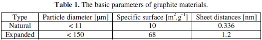
In our research we have used two types of crystalline graphite: natural and expanded graphite (see main properties in Table 1).
These two graphite types represent the most widely used materials for negative electrode in lithium-ion batteries. Our idea is to prepare a graphite electrode that already contains lithium atoms before the first charging cycle. These lithium atoms can be used and consumed to SEI layer creation. The lithium atoms which are in graphite are used in the first and second charge-discharge cycles. The entire capacity of positive electrode is preserved and its lithium atoms can be used for charge transfer [2,8,9,11,12].
Experimental setup
Our work is divided into three parts which describe three different lithiation methods. The first part presents the experiment process, where n-butyllithium reagent as donor of lithium atoms is used. The measurements showed, despite our hypothesis, that n-butyllithium is now able to reduce graphite material, i.e., inserting lithium atoms among graphite sheets. The second part of our research is based on the results obtained in the first part. In this experiment we have used the ionic compound FeCl3 as lithium attractor. Along with our assumption, the ionic molecule had tear off the lithium atom from butyl chain. The separated lithium atom should be easier inserted or bonded to the graphite structure. The third part performs a special lithiation process that is based on conductive contention between the graphite electrode and metal lithium. If the graphite electrode is dipped in an aprotic electrolyte together with the metal lithium, we get a half-cell with an electrochemical potential of approximately 2.5 V. This way, the prepared half-cell can be connected via outer conductor; if this is done, the electric current begins to flow through the conductor. Based on the electrochemical potential of the cell, the lithium cations are transported through the electrolyte to graphite electrode where they are reduced from outer circuit. In this case, we call it electroless lithiation process [1,5,3,7].
Manufacturing process
This section describes the steps of manufacturing process which were used to preparing lithiated graphite. The manufacturing process is focused on doping graphite by lithium ions. The lithiated graphite material served as precursor for preparing the final graphite electrode. All steps were carried out under inert atmosphere of argon. The n-butyllithium reagent used in our experiments contains 2.5 molar concentration of n-butyllithium dissolved in n-hexane. An electrolyte containing 1 molar concentration of LiPF6 salt was used in all the experiments [13,14].
A. Lithiation with help of n-butyllithium
1. Graphite material was dried at a temperature of 150 °C for 12 hours in a vacuum chamber. This step is necessary to remove the residual moisture from graphite. The n-butyllithium is very reactive with water.
2. Addition of the n-butyllithium reagent into the graphite. The molar ratio was calculated: one Li atom per six carbon atoms - LiC6.
3. The mixture of n-butyllithium and graphite was stirred for 24 hours under room temperature.
4. Following up the prior stirring step, the mixture was filtered. The lithiated graphite blend was purged using n-hexane solvent in order to remove its nbutyllithium residues. The mixture is stirred with n-hexane for 6 hours.
5. After the purging step, the mixture was a second time filtered. Now, the lithiated graphite is in its final state (precursor for preparing the testing electrode) and it should not contain any residues.
B. Lithiation with help of n-butyllithium and iron(III) chloride (FeCl3) attractor
1. Graphite material was dried at a temperature of 150 °C for 12 hours in a vacuum chamber.
2. The FeCl3 compound has been dried in a vacuum chamber at a temperature of 150 °C for 24 hours. It is very important to remove the residual moisture from FeCl3 powder.
3. Both dried components (graphite and FeCl3) were mixed together in an exact ratio. The ratios were calculated as follows: one hexagonal unit (C6) of graphite per one FeCl3 molecule. The two ratios of the components were prepared as follows:
- first ratio, ten carbon atoms per one FeCl3 molecule, ratio 10:1.
- second ratio, six carbon atoms per one FeCl3 molecule, ratio 6:1. Each composition ratio was stirred with n-hexane for 24 hours, this process making the composition more homogeneous.
4. The mixture that contains the exact ratio of graphite/FeCl3 and n-hexane was filtered and dried in order to remove n-hexane solvent.
5. Addition of the n-butyllithium reagent into the mixture. The molar ratio was calculated: one Li atom per six carbon atoms - LiC6. The following process steps are the same as in paragraph A, point 3 (above).
C. Electroless lithiation process
1. Graphite material was dried at a temperature of 150 °C for 12 hours in a vacuum chamber.
2. The negative electrode was prepared from the dried graphite material. For improving of material properties, 10 wt% of binder (polyvinylidenefluoride - PVDF) were added to the graphite material.
3. Electrode material was coated onto copper foil (thickness 35 μm) and was sintered at the temperature of 50 °C for 24 hours.
4. The prepared electrode was connected to the system that is shown in Fig. 7. During this step, the electrode material was reduced by lithium ions for 48 hours, from the potential of 2.5 V up to 100 mV.
5. In the last stage of this process, the electrode material was stripped off from the copper collector and dried out under room temperature. This lithiated material was used like a precursor for preparing the testing electrode.
Experimental results
In our experiments we have used two types of graphite: expanded graphite (manufacturer Bochemie, a.s.) and natural graphite - COND CR5995 (manufacturer Graphite Tyn.). The main parameters of each graphite type are listed in Table 1.
Graphite lithiation with help of n-butyllithium
This section deals with preparing negative electrodes from prelithiated graphite. These electrodes were made for experimental and measurement purposes. The manufacturing process begins from the precursor (lithiated graphite material), which was obtained by lithiation process, as quoted above.
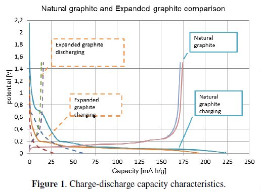
Through the manufacturing steps, we have got the lithiated graphite material in powder form. The lithiated graphite powder was mixed with PVDF binder. The binder was calculated as 10wt% of lithiated graphite material and must be dissolved in N-methyl-2-pyrrolidone (NMP) solvent. The electrode mixture was stirred for 24 hours. After stirring the blend (mixture) was coated on a copper foil (thickness 35 μm). The wet thickness of the coated layer was 80 μm; in the next step the coated blend was sintered for 12 hours at the temperature of 50 °C. As final step of the electrode manufacturing process small rounded electrodes with 18 mm diameter were cut off. These electrodes were pressed by a pressure of 2 tons per cm2. The electrodes were subsequently measured on a potentiostat /galvanostat instrument in a half-cell system. Arrangement of the electrodes was as follows: working electrode (WE) connecting to analysed electrode, counter electrode (CE) was represented by metal lithium. At the beginning of the two types of graphite were measured and compared, before being used in our experiments (see Fig. 1).
The graph displayed in Fig. 2 shows measured characteristics of expanded graphite.
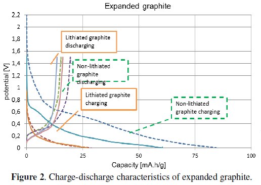
The graph compares the characteristics of lithiated and non-lithiated material. The electrode which was made from nonlithiated material (dashed curve) has got about 20% higher capacity than the lithiated one (solid line).
The graph presented in Fig. 3 shows the measured characteristics of natural graphite.
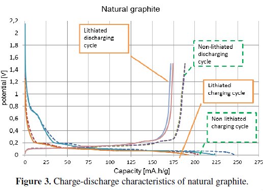
The electrode which was made from non-lithiated material (dashed curve) has higher capacity than the lithiated one (solid line), as in the previous case. Natural graphite has not got the difference of capacity as big as in the case of the expanded graphite [1,4].
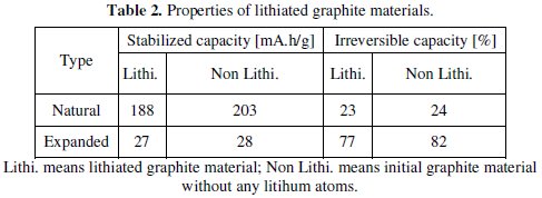
The both types of graphite electrodes (lithiated and non-lithiated) have got approximately similar irreversible capacity. The non-lithiated natural graphite material has an irreversible capacity of around the 24 %, and the lithiated one has an irreversible capacity of around 23 %, see Fig. 3. The more noticeable difference can be seen in the case of expanded graphite, Fig. 2. The non-lithiated electrode material has an irreversible capacity of around 82 %, and the lithiated electrode material has around 77 %. The summarized results are listed in Table 2.
Graphite doped with iron(III) chloride (FeCl3)
The experiments presented in this section are based on the results obtained in the previous section (Graphite lithiation with help of n-butyllithium). In Table 2 it is clearly seen the poor capacity characteristics of expanded graphite; the following experiments were carried out with natural graphite CR 5995 provided by Graphite Tyn company. In terms of irreversible capacity, only a slight difference between lithiated and non-lithiated graphite material was observed. There is a missing intercalation reaction between n-butyllithium reagent and the graphite material.
In the other experiments the ionic compound iron(III) chloride (FeCl3) was used. FeCl3 belongs to halides group. Halides are binary compounds, of which one part is a halogen atom and the other part is an element which is more electropositive. The halide group contains the significant compounds copper(II) chloride (CuCl2), manganese(II) chloride (MnCl2) and cobalt(II) chloride (CoCl2). All of these compounds are suitable for using in a lithiation process. We have decided to use FeCl3 due to its three chloride atoms which cause partial distribution of the charge [3,4]. The manufacturing process of the electrode material has been previously described. It was coated on a copper foil with the addition of a binder. The manufacturing process of the electrodes is the same as described in previous the case. The electrodes were subsequently measured on a potentiostat /galvanostat instrument (Bio-Logic) in a half-cell system. The measured characteristics are displayed in Fig. 4 and Fig. 5.
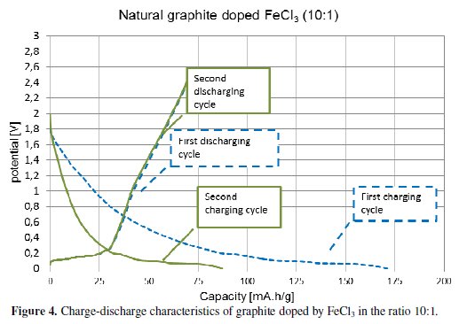
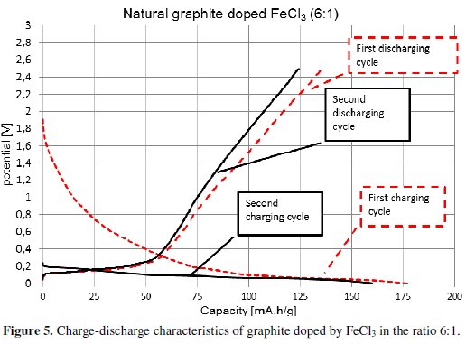
The obtained results show the capacity characteristics of the measured specimens. The electrode material with the ratio 10:1 (ten carbon atoms per one atom of FeCl3) has lower stable capacity (around 85 mA.h/g) and higher irreversible capacity (58 %) than the electrode material with the ratio 6:1, see Fig. 4. The material with the ratio 6:1 has a stable capacity of around 160 mA.h/g, and an irreversible capacity of 15 %, see Fig. 4. This marked difference of the material characteristics is evident from Fig. 6 and Table 3.
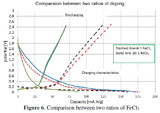
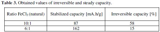
The differences of capacity characteristics are displayed in Fig. 6. Measured results of that experiment are given in Table 3 and Table 4.
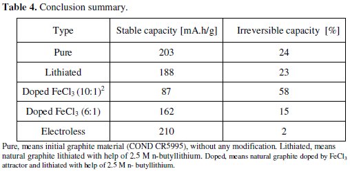
Pure, means initial graphite material (COND CR5995), without any modification. Lithiated, means natural graphite lithiated with help of 2.5 M n-butyllithium. Doped, means natural graphite doped by FeCl3 attractor and lithiated with help of 2.5 M n-butyllithium.
Electroless lithiation process
The previous experiments give only a small improving of the irreversible capacity as well as of the material characteristics. There is only negligible improvement of irreversible capacity along with steady material capacity. This third section deals with the simple lithiation method that is based on the potential of the electrochemical cell. The electrochemical potential is formed between the graphite electrode (material based on graphite with additives that is plated on the copper collector) and the electrode from metal lithium [6,7,10]. This half-cell is connected through a wire that serves as outer conductor of electron (see Fig. 7).
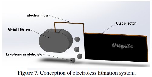
The system presented in Fig. 7 was used in our process of electrode material manufacturing. As an electrolyte it was used 1 M concentration of LiClO4 salt (dissolved in a mixture of DMC and EC, as described above). This way, the prepared material was coated by the electrode collector, following the steps described formerly. Capacity characteristics obtained from pre-lithiated graphite are shown in Fig. 8.
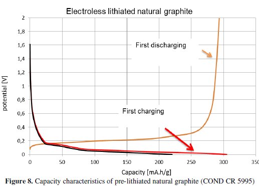
The values of irreversible and steady capacity, measured with the help of the electroless lithiation process, brought significant improvement. This lithiation process fully saturated the graphite structure by lithium atoms. These atoms are used during the electrode formation (they are consumed in the development of the SEI layer on the heterogeneous interphase electrode/electrolyte); also, they prepare the positions inside the graphite structure for the other lithium atoms in the subsequent charge-discharge cycles.
Conclusions
In the first part of our experimental work (Graphite lithiation with help of nbutyllithium) we describe the lithiation process with the help of n-butyllithium reagent. In the experiments two graphite kinds were used: expanded and natural (CR5995) graphite, see Table 1. Fig. 2 and Fig. 3 show the comparison between lithiated and non-lithiated materials. The expanded graphite shows decrease of capacity which can be caused by the sheet distances extension occurred during the lithiation process. The expanded graphite was taken out from other experiments due to its small and high irreversible capacity, see Fig. 1. The natural graphite does not show this marked difference at capacity characteristics. The irreversible capacity of natural graphite was slightly improved from 24 % to 23 %. The n-butyllithium is a too feeble reduction agent for graphite. The Li+ atoms are not able to separate from n-butyl chain and intercalating to graphite. The second part of our work (Graphite doped by iron(III) chloride (FeCl3)) uses the iron(III) chloride ionic compound like a lithium attractor. Obtained results are listed in Table 3. The most suitable ratio of iron(III) chloride is 1:6, i.e., one molecule of FeCl3 per six carbon atoms (similar as non-stoichiometric compound LiC6). This experiment with ionic compound got decreasing of irreversible capacity from 24 % to 15 %.
The last part of our work (Electroless lithiation process) brought the expected characteristics, see Fig. 8. The irreversible capacity of natural graphite decreased from 24 % to 2 %.
The overall results are summarized and compared in Table 4. Our experiments confirm that the idea of irreversible capacity decreasing by using pre-lithiated graphite material works. The electroless lithiation method for preparing pre lithiated electrode material is theme to discussion. Its utilization and application in commercial area can be difficult but it can bring higher capacities and better characteristic of lithium-ion batteries.
References
1. Yazami R. Synthetic Met. 1987;20:383-386. [ Links ]
2. Zhao L, Watanabe I, Doi T, et al. J Power Sources. 2006;161:1275-1280. [ Links ]
3. Dines MB. Mater Res Bull. 1975;10:287-291. [ Links ]
4. Yazami R. Synthetic Met. 1983;7:169-176. [ Links ]
5. Hung CC. Carbon. 1995;33:315-322. [ Links ]
6. Ratnakumar BV, Smart MC, Surampudi S. J Power Sources. 2001;9798:137-139. [ Links ]
7. Sang-Pil K, Adri CT, Van D. et al. J Power Sources. 2011;196:8590-8597. [ Links ]
8. Smart MC, Ratnakumar BV, Surampudi S, et al. J Electrochem Soc. 1999;146:3963-3969. [ Links ]
9. Sivakkumar SR, Pandolfo AG. Electrochim Acta. 2012;65:280-287. [ Links ]
10. Holzapfel M, Martinent A. J Electroanal Chem. 2003;546:41-50. [ Links ]
11. Huang S, Fan F, Li J, et al. Acta Mater. 2013;61:4354-4364. [ Links ]
12. Malmgren S, Ciosek K, Lindblad R, et al. Electrochim Acta. 2013;105:8391. [ Links ]
13. Wang HY, Wang FM. J Power Sources. 2013;233:1-5. [ Links ]
14. Swiatowska J, Lair V, Pereira-Nabais C, et al. Appl Surf Sci. 2011;257:9110-9119. [ Links ]
Acknowledgements
This work was supported by the project Support for human resources and transfer of knowledge in conditions of international cooperation of research teams CZ.1.07/2.3.00/20.0103, Grant Agency of Czech Republic, Project P102/10/2091 (Increase the safety of lithium-ion batteries) and specific research FEKT-S-11-7 (Materials and technologies for electronics).
*Corresponding author. E-mail address: xlibic00@stud.feec.vutbr.cz
Received 1 July 2013; accepted 23 December 2013

