


Serviços Personalizados
Journal
Artigo
 Inglês (pdf)
 Artigo em XML
 Referências do artigo
 Enviar este artigo por email
Indicadores
-
 Citado por SciELO
 -
 Acessos
Links relacionados
-
 Similares em
SciELO
Similares em
SciELO
Compartilhar

 Permalink
Portugaliae Electrochimica Acta
versão impressa ISSN 0872-1904
Port. Electrochim. Acta v.28 n.4 Coimbra 2010
Electrochemical Degradation and Cyclic Voltammetric Studies of Textile Reactive Azo Dye Cibacron Navy WB
P. Kariyajjanavar,1,* J. Narayana,1 Y. A. Nayaka,2 M. Umanaik2
1 Department of P.G. Studies & Research in Environmental Science, Kuvempu University, Jnana Sahyadri, Shankaraghatta, 577 451 Karnataka, India
2 Department of P.G. Studies & Research in Chemistry, Kuvempu University, Jnana Sahyadri, Shankaraghatta, 577 451 Karnataka, India
DOI: 10.4152/pea.201004265
Abstract
The removal of pollutants from effluents by electrochemical degradation has become an attractive method in recent years. This paper deals with the removal of reactive textile dye Cibacron Navy W-B (CNWB) from an aqueous medium by the electrochemical method using graphite carbon electrodes. Electrochemical behavior of reactive azo dye CNWB was performed with cyclic voltammetry in sulphuric acid medium using glassy carbon as working electrode. The potential range selected for the dye was in the range +700 mV to –450 mV. The voltammetric curve of CNWB shows cathodic peaks at +50 mV, –155 mV and –317 mV and anodic peaks at +382 mV and +547 mV, respectively. The decolourisation efficiency was assessed through UV-Visible studies. The LC-MS of the dye were analyzed before and after electrochemical treatment and confirmed that the azo groups and aromatic rings were destroyed. The effect of pH and nature of supporting electrolytes on the electrochemical degradation of dye was also studied. The maximum Chemical Oxygen Demand (COD) removal efficiency was ~100% for the dye solutions at 5 gL-1 of NaCl concentration. The results revealed the suitability of the present process for the effective degradation of dye effluents.
Keywords: carbon electrodes; cyclic voltammetry; reactive azo dye; electrochemical degradation; LC-MS.
Introduction
Large amounts of various dyes are being used in the textile industries for dyeing purpose. Among the dyes’ family, more than half are azo compounds. Reactive azo dyes are generally, water soluble anionic and constitute 20-40% of dyes used for dyeing cellulosic fibers, such as cotton and rayon, but are also used for silk, wool, nylon, and leather [1-2]. Reactive dyes contain one or more reactive groups capable of forming covalent bonds with hydroxyl or amino group present on fiber. Dye is the most difficult to treat constituent of the textile wastewater. At the end of the dyeing process, due to its poor exhaustion properties, as much as 30% of initial dye applied, remain unfixed and end up in effluents [3-4]. The presences of unfixed dyes are perceived as one of the major environmental problems of textile wastewater and therefore it needs to be removed from the wastewater before it is discharged to the environment [5]. Since dyes are carcinogenic and toxic, they imbalance the chemical and biological nature when they are discharged into the water bodies [6]. Due to the large amounts of effluents discharged from textile industries, it is under considerable pressure to minimise the water consumption and to reduce the treatment cost.
Conventionally textile wastewater is being treated through biological, physical and chemical methods [7]. Biological treatment processes are often ineffective in removing dyes which are highly structured polymers with low biodegradability [8]. However, various physico-chemical techniques, such as chemical coagulation, adsorption on activated carbon, reverse osmosis and ultra filtration, are also available for the treatment of textile wastewater, but those latter are limited by the low concentration ranges [9]. Further, the main drawbacks of chemical coagulation are the addition of other chemicals. In recent years, ozonation [10] and photooxidation [11-12] have been proposed as alternative methods, but the high cost of these methods leads to further consideration.
In this context, electrochemical technique is considered to be a powerful means of pollution control for the treatment of textile wastewater. Indeed, electrochemical method has been successfully tested [13] and it has certain significant advantages such as simple equipment, easy operation, lower operating temperature, etc. [14-16]. The process requires significantly less area and equipment than the conventional biological treatment processes [17-18]. It is relatively a new trend in the azo dyes wastewater management with promising results [8,19].
Several researchers have investigated the feasibility of electrochemical degradation of dyes with various electrode materials such as titanium-based DSA electrodes [20], platinum electrode [21], diamond and metal alloy electrodes [22], boron doped diamond electrodes [23] and electrocoagulation of dye effluents with aluminum and iron electrodes [24]. In the past, graphite was frequently used as an anode during electrochemical treatment of dye solution as it is relatively economical and gives satisfactory results.
The aim of this work was to test the feasibility of electrochemical method for the degradation of reactive dye Cibacron Navy W-B (CNWB).
Experimental part
Materials
Cibacron Navy W-B (CNWB) (commercial name), a reactive dye (CAS No. 17095-24-8, MW=991.816 gmol-1, 70-80% Purity) was obtained from textile industry, Himatsigka Linens, Hassan, Karnataka. All other chemicals used for experiments are of analytical grade reagent, obtained from s d fine chem-limited, Mumbai, India. Cylindrical carbon electrodes (chemical composition: graphite carbon + coke: 85% and ash 15%) were obtained from Power Cell Battery India Limited. A digital DC power supply (AD 302S: 30V, 2A) was used as an electrical source. Double distilled water was used to prepare the desired concentration of dye solutions and of the reagents.
Instrumentation
Cyclic voltammetric studies
The electrochemical measurements were carried out using an Electroanalyser, model-201(ChemiLink, Mumbai, India) controlled by electrochemical software. A three electrodes system was used for the cyclic voltammetric experiments. The working electrode was a highly polished glassy carbon disc, with an effective surface area of 0.06 cm2. A platinum wire and saturated calomel were used as counter and reference electrodes, respectively.
Electrochemical degradation studies
Fig. 1 shows the experimental setup for the electrolysis. Graphite carbon electrodes of 4.5 cm length and 0.8 cm diameter were used as anode and cathode. The effective electrode area was 11.87 cm2. Different supporting electrolytes such as NaCl and Na2SO4 were added to the electrolytic cell to increase the conductivity of the solution and to decrease the electrolysis time. The solution was kept under agitation using a magnetic stirrer.
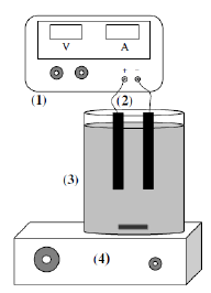
Figure 1. Schematic diagram of the experimental setup (1, DC power supply; 2, electrode pair; 3, electrolytic cell; 4, magnetic stirrer.
UV-Visible studies
A UV-Vis Spectrophotometer (ELICO, SL-159) was employed to measure the absorbance at maximum wavelength (λmax=596) for dye solutions before and after electrolysis. The decolourisation efficiency was calculated using the relation:
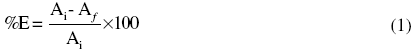
where, Ai is the initial absorbance value and Af is the final absorbance value with respect to their λmax or Ai and Ai are initial and final COD values of the dye solution, respectively.
pH and conductivity measurement
Water analyzer (Systronics, Model-371) was used to measure the pH and conductivity of the dye solution before and after electrolysis under different electrolytic condition.
Liquid Chromatography-Mass Spectrometry studies (LC-MS)
Extent of degradation of the dye samples was analyzed by LCMS-2010A, Shimadzu, Japan. The LC-MS was fitted with column C18. The mobile phase was methanol: water (90:10). The flow rate was 0.2 mLmin-1 and the injection volume of dye was 5 µL. The dye solutions were injected into LC column before and after electrolysis. Analyses using ESI (electron spray ionization) interface were done under the same chromatographic conditions as described for the APCI (atmospheric pressure chemical ionization) analysis, except the guard column, which was not used in the ESI analysis.
Results and discussion
The structure of reactive azo dye CNWB is shown in Fig. 2. The dye contains two sulphonic acid groups, which increase the water solubility of the dye, two azo groups, one hydroxyl group and one amide group, which are responsible for the relative stability of azo groups, and two (–SO2–(CH2)2–O–) groups, which provide a strong adherence to the textile substrate [20].
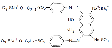
Figure 2. Molecular structure and chemical name of the reactive azo dye CNWB.
Cyclic voltammetric studies
Cyclic voltammagrams of CNWB (0.05 mM) were recorded in 2.52 mM H2SO4 using glassy carbon as working electrode. The potential range selected was in the range +700 mV to –450 mV. Three cathodic peaks (Ic, IIc and IIIc) in the forward scan and two anodic peaks (Ia, IIa) in the reverse scan, indicated quasi-reversible electrochemical nature of the dye (Fig. 3).
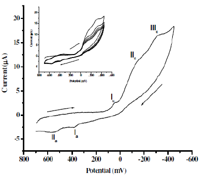
Figure 3. Cyclic voltammograms of 0.05 mM CNWB dye in 2.52 mM H2SO4 on GCE; scan rate: 100 mVs-1; Inset plot: multiple scan.
The voltammetric curve of CNWB shows cathodic peaks at +50 mV, –155 mV and–317 mV, and anodic peaks at +382 mV and +547 mV at the scan rate of 100mVs-1. The cathodic peak current observed for CNWB is attributed to the reduction of azo groups to amines in a single step. These data are very important to assess the feasibility of the electrochemical process for the degradation of azo dyes. The probable mechanism for the reduction process is as follows:
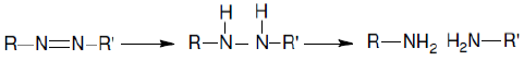
Fig. 4 shows the effect of scan rate on the cyclic voltammogramm of CNWB. The reduction peak current increased linearly with square root of the scan rate (υ1/2). Inset plot of cathodic peak current (IIIpc) (r2= 0.9905) versus (υ1/2), indicates the diffusion controlled process. The difference between the anodic and cathodic peak potentials, δEp, has been increased with the scan rate.
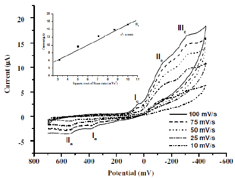
Figure 4. Cyclic voltammograms for 0.05 mM CNWB dye in 2.52 mM H2SO4 on GCE with increasing scan rate. Inset plot: linear relationship between the cathodic peak current (IIIc) versus with increasing υ1/2.
Electrochemical degradation studies
The electrochemical degradation under optimal electrolyte conditions resulted in fast and almost complete decolourisation of the dye. After electrochemical treatment, the percentage of decolouration CNWB was found to be ~100% in 20 min. The degree of decolouration was monitored through UV-Vis absorbance studies.
Effect of pH
In order to study the effect of pH on the degradation of CNWB, the solution pH was varied from 3-11 by the addition of 0.2 N H2SO4 or NaOH solution. The reactions were carried out for 20 min at a dye concentration of 50 ppm (w/v) and NaCl concentration of 7 gL-1, a current density of 100 Am-2 at room temperature (315 K). After electrolysis the final pH was attained almost constant in acidic condition and decreased at neutral and basic conditions. The decolouration efficiency of CNWB was increased in acidic pH and decreased in both neutral and basic pH (Fig. 5). Therefore, pH 3 was maintained in subsequent experiments.
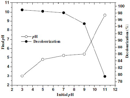
Figure 5. Effect of pH on decolourisation(—°—) and final pH(—·—): electrolysis time 20 min, dye solution 50 ppm(w/w), NaCl 7 gL-1 and room temperature (315 K).
Effect of supporting electrolytes
Fig. 6 shows the effect of supporting electrolytes (NaCl and Na2SO4) on decolouration efficiency with twenty minutes of electrolysis time keeping the pH at 3 and the current density at 100 Am-2. It can be seen that in the presence of NaCl, the decolouration efficiency was increased with a subsequent decrease in the applied voltage. From this observation it was concluded that the introduction of Cl¯ containing electrolytes can enhance the degradation efficiency and shortens the electrolysis time, which may be attributed to the reaction between the generated chlorine/hypochlorite and the dye molecule. The proposed mechanism is as follows:
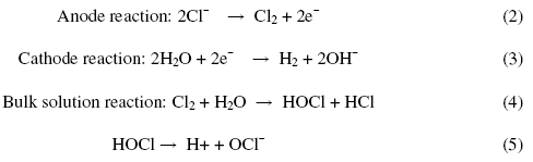
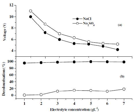
Figure 6. Decolourisation efficiency of dye CNWB in the presence of different electrolytes with increasing the weight of supporting electrolytes in twenty minutes of electrolysis.
Based on these studies, the optimum concentration of NaCl was found to be 5 gL-1. With increase in the concentration of NaCl (>5 gL-1) there was a slight improvement in the decolouration efficiency (Fig. 6b) with a decrease in the operating voltage (Fig. 6a).
Analysis of COD
The standard COD measurement is known to be affected by a number of inorganic substances which are outlined in standard methods for the examination of water and wastewater [20]. Of these, chloride may have a significant effect on the test, due to its reaction with potassium dichromate [21]. The COD was measured by adopting the open reflux titrimetric method. In the present study it can be assumed that the removal of CNWB from their aqueous solutions may proceed by indirect electrochemical oxidation rather than by direct electrochemical process. The electrolysis was carried out at a current density of 100 Am-2. At this current density, Cl2 generated in the solution drives the oxidation process. The Cl2 species is a powerful oxidizing agent capable of oxidizing the dyestuffs. In absence of chloride containing electrolytes, the COD removal and dye degradation efficiency were very low [22]. The percent removal of COD increased with increase in NaCl concentration (Fig. 7b). This confirmed that the electrogenerated chlorine/hypochlorite will play an important role in the electrocatalytic degradation process of the dyestuffs. The maximum COD removal efficiency was observed at pH 3 (Fig. 7a).
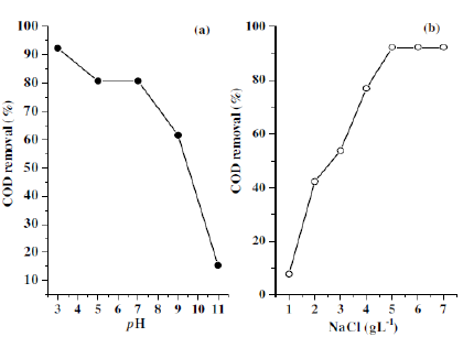
Figure 7. Effect of pH (a) and NaCl concentration (b) on removal of COD of CNWB dye 50 ppm(w/w).
UV-Vis studies
Fig. 8-10 show UV-Vis absorption spectra for CNWB dye solution before and after electrolysis. The UV-Vis spectrum of the dye solution was scanned and the λmax was found to be 596 nm. The decolouration of dye solution was increased with electrolysis time and complete decolouration was observed in 20 min of electrolysis at pH 3 (Fig. 8). During electrochemical degradation, the cleavage of —N=N— bonds and aromatic rings has taken place, which results in the decrease of the absorbance band of the dye solution. Also the absorption band has been shifted from visible to UV region, which indicated the degradation of large dye molecule into smaller fragments [23].
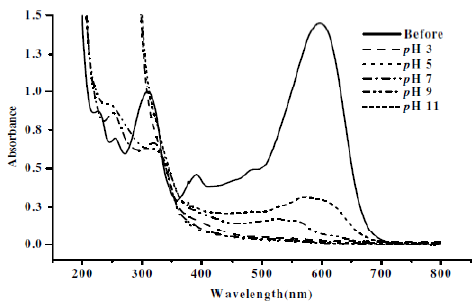
Figure 8. Absorption spectra for CNWB dye solution before and after electrolysis (20 min) at different pH in NaCl 7gL-1.
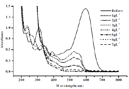
Figure 9. Absorption spectra for CNWB dye solution before and after electrolysis (20 min) at different concentrations of NaCl keeping pH 3 constant.
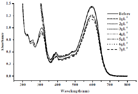
Figure 10. Absorption spectra for CNWB dye solution before and after electrolysis (20 min) at different concentrations of Na2SO4 keeping pH 3 constant.
The intensity of absorbance at λmax=596 nm was decreased with increase in the concentration of NaCl (Fig. 9). The degradation efficiency was found to be low in presence of Na2SO4 (Fig. 10). The maximum degradation efficiency in presence of NaCl is attributed to the indirect electro-oxidation of CNWB by the active chlorine, which was electrogenerated at the anode surface. However, the active chlorine can lead the partial mineralisation of dyes [24].
LC-MS studies
The LC-MS analysis of the dye was carried out before and after electrolysis to investigate the degradation process. Before electrochemical treatment MS spectrum shows more number of peaks due to the presence of other impurities (Fig. 11). The LC-MS spectrum of electrolysed dye solution shows the absence of earlier peaks, indicating that the entire dye has been decomposed to colourless low molecular weight fragments (Fig. 12).
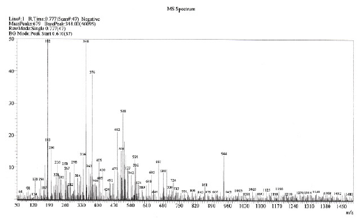
Figure 11. Mass spectrum of 70-80% reactive dye CNWB before electrolysis.
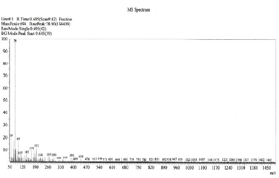
Figure 12. Mass spectrum of 70-80% decolourised reactive dye CNWB after electrolysis.
Electric energy consumption
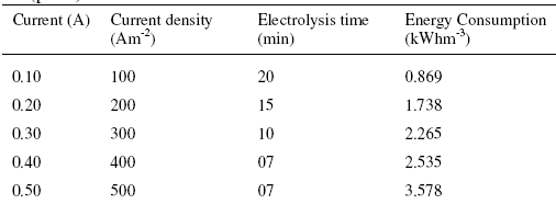
The major operating cost is associated with electrical energy consumption during electrochemical degradation process. The electric energy consumption (E), required to decompose CNWB dye solution of 50 ppm (w/v) concentration at various current densities, was calculated in terms of kWhm-3 using the relation:
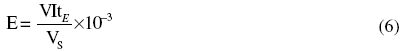
where V is the applied voltage(V), I is the applied current (A), tE is the electrolysis time (h) and Vs is the volume of dye solution (m3). As per the results the minimum electrical energy consumption was 0.869 kWhm-3 at 100 Am-2 current density. At higher current densities, the energy consumption was found to be increased, which may be attributed to the increased hydrogen and oxygen evolution reaction (Table 1).
Table 1. The electric energy consumed during the degradation of 50 ppm (w/v) CNWB dye solution (pH 3) at various current densities.
Conclusions
In the present work the electrochemical method has been explored for the degradation of CNWB using graphite carbon electrodes as anode and cathode. Optimum operational conditions for the effective degradation of CNWB were: current density 100 Am-2; NaCl concentration of 5 gL-1; and temperature 300.15 K. Cyclic voltammograms indicated the quasi-reversible electrochemical nature of CNWB. The effect of conducting salt clearly showed that, introduction of Cl¯ containing electrolytes enhances the degradation efficiency of the dye. UV-Vis and MS spectral studies confirmed that the proposed electrochemical degradation process is an effective method for the degradation of CNWB.
Acknowledgements
The Authors are grateful to DBT and UGC, New Delhi, for the financial support extended. Also grateful to Kuvempu University, Power Cell Battery India Limited, Himatsingka Linens, Karnataka and Textiles Huntsman International India Pvt. Ltd., Bombay for their support to carry out this work.
References
1. W.A. Rearick, L.T. Farias, H.B.G. Goettsh, Textile Chem. Color 29(4) (1997) 10-19. [ Links ]
2. S. Zhemin, W. Wenhua, J. Jinping, Y. Jianchang, F. Xue, P. An, J. Hazard. Mater. 84(1) (2001) 107-116. [10.1016/S0304-3894(01)00201-1]
3. W. Somasiri, W. Ruan, L. Xiufen, C. Jian, EJEAFChe 5(1) (2006) 1224-1234.
4. L. Laasri, M.K. Elmrani, C. Omar, Env. Sci. Pollut. Res. 14(4) (2007) 237-240. [10.1065/espr2006.08.331]
5. U. Pagga, D. Brown, Chemosphere 15(4) (1986) 479-491. [10.1016/0045-6535(86)90542-4]
6. A.G. Vlyssides, M. Loizidou, P.K. Karlis, A.A. Zorpas, D. Papaioannou, J. Hazard. Mater. 70 (1-2) (1999) 41-52. [10.1016/S0304-3894(99)00130-2]
7. B. Armagan, O. Ozdemir, M. Turan, M.S. Celik, J. Chem. Technol. Biotechnol. 78(7) (2003) 725-732. [10.1002/jctb.844]
8. A. Sakalis, D. Ansorgova, M. Holapek, P. Jandera A. Voulgaropoulos, Intern. J. Environ. Anal. Chem. 84(11) (2004) 875-888. [10.1080/03067310310001626731]
9. N. Daneshwar, H.A. Sorkhabi, M. Kobya, J. Hazard. Mater. 112(1-2) (2004) 55-62. [10.1016/j.jhazmat.2004.03.021]
10. J.S. Do, M.L. Chen, J. Appl. Electrochem. 24(8) (1994) 785-790. [10.1007/BF00578095]
11. J.P. Lorimer, T.J. Mason, M. Plates, S.S. Phull, Ultrason. Sonochem. 7(4) (2000) 237-242. [10.1016/S1350-4177(99)00045-0]
12. H. Ma, B. Wang, X. Luo, J. Hazard. Mater. 149(2) (2007) 492-498. [10.1016/j.jhazmat.2007.04.020]
13. S.J. Allen, K.Y. H. Khader, M. Bino, J. Chem. Technol. Biotechnol. 62(2) (1995) 111-117. [10.1002/jctb.280620202]
14. L. Fan, Y. Zhou, W. Yang, G. Chen, F. Yang, Dyes and Pigments 76(2) (2008) 440-446. [10.1016/j.dyepig.2006.09.013]
15. L. Szpyrkowicz, C. Juzzolino, S. N. Kaul,.S. Daniele, M.D. De Faveri, Ind. Eng. Chem. Res. 39(11) (2000) 3241-3248. [10.1021/ie9908480]
16. M.A. Sanroman, M. Pazos, M.T. Ricart, C. Cameselle, Chemosphere 57(3) (2004) 233-239. [10.1016/j.chemosphere.2004.06.019]
17. M.C. Rivera, M.M.D. Jimenez, M.P.E. Gonzalez, Chemosphere 55(1) (2004) 1-10. [10.1016/j.chemosphere.2003.10.060]
18. A. Fernandes, A. Morao, M. Magrinho, A. Lopes, I. Gonçalves, Dyes and Pigments 61(3) (2004) 287-296. [10.1016/j.dyepig.2003.11.008]
19. M. Kashefialasl, M. Khosravi, R. Marandi, K. Seyyedi, Int. J. Environ. Sci. Tech. 2(4) (2006) 365-371.
20. S.C. Lenor, E.G. Arnold, D.E. Andrew, Standard Methods for the Examination of Water and Wastewater: 20th edition, (APHA/AWWA/WEF, Washington DC, USA) 1999.
21. E. Chatzisymeon, N.P. Xekoukoulotakis, A. Coz, N. Kalogerakis, D. Mantzavinos, J. Hazard. Mater. 137(2) (2006) 998-1007. [10.1016/j.jhazmat.2006.03.032]
22. N.M.A. Ghalwa, M.S. Abdel-Latif, J. Iran. Chem. Soc. 2(3) (2005) 238-243.
23. F. Abdelmalek, M. R. Ghezzar, M. Belhadj, A. Addou, J.-L. Brisset, Ind. Eng. Chem. Res. 45(1) (2006) 23-29. [10.1021/ie050058s]
24. F. Yi, S. Chen, C. Yuan, J. Haz. Mater. 157(1) (2008) 79-87. [10.1016/j.jhazmat.2007.12.093]
Received 18 March 2010; accepted 31 August 2010
* Corresponding author: prakashsk2678@yahoo.co.in

