


Serviços Personalizados
Journal
Artigo
 Inglês (pdf)
 Artigo em XML
 Referências do artigo
 Enviar este artigo por email
Indicadores
-
 Citado por SciELO
 -
 Acessos
Links relacionados
-
 Similares em
SciELO
Similares em
SciELO
Compartilhar

 Permalink
Ciência & Tecnologia dos Materiais
versão impressa ISSN 0870-8312
C.Tecn. Mat. v.22 n.3-4 Lisboa jul. 2010
On a unified fatigue modelling for structural analysis based on the shakedown concept
K. Dang Van
Mecamix, X-Tech
Ecole Polytechnique, 91128 Palaiseau, France
ABSTRACT
Fatigue analysis of structures requires nowadays specific numerical tools able to take account of complex multiaxial loadings generated by the use of FEM structural calculations. Traditionally fatigue is studied in different ways depending on the fatigue regime and the field of interest: fatigue limit analysis, life prediction in high or low cycle fatigue, thermal fatigue The application of the shakedown theory to the analysis of the fatigue problems permits to present a unified theoretical background to both high and low cycle fatigue. This point of view allows interpreting all types of industrial problems of fatigue in an efficient manner. The description of the stabilised mechanical state after shakedown at macroscopic and mesoscopic scales gives access to engineering values which will drive the fatigue damage of the structure. The formulations are intrinsic and suffer no ambiguities. Some examples of fatigue analysis for different industrial areas are presented.
Keywords: Fatigue, shakedown.
RESUMO
A análise à fadiga de estruturas exige actualmente ferramentas numéricas específicas, capazes de tomar em consideração os carregamentos multiaxiais complexos gerados pelo uso de cálculos estruturais baseados no método dos elementos finitos. Tradicionalmente, a fadiga é estudada de diversas formas dependendo do regime de fadiga e do campo de interesse: análises baseadas no limite de fadiga, previsão de vida em fadiga a alto ou baixo número de ciclos, fadiga térmica . A aplicação da teoria do shakedownà análise de problemas de fadiga permite apresentar um contexto teórico unificado para fadiga a alto e baixo números de ciclos. Este ponto de vista permite interpretar, de uma maneira eficiente, todos os tipos de problemas industriais envolvendo fadiga. A descrição do estado mecânico estabilizado depois de shakedwonàs escalas macroscópicas e mesoscópicas dá acesso a dados de engenharia que condicionam a danificação por fadiga da estrutura. As formulações são intrínsecas e não sofrem de ambiguidades, Alguns exemplos de análise à fadiga para diversas áreas industriais são apresentados.
Palavras chave: fadiga; shakedown.
1. Introduction
One of the main goals in structural design is to avoid rupture due to fatigue. During a long period, and still now, engineers used simple stress approaches. Uniaxial criteria like S-N curves, Goodmann-Haigh diagrams, Kt- Kf concept are sufficient when the stresses are derived by using analytical elastic approaches like beam theory. The generalization of FEM calculations make possible to characterise with more accuracy the stress and strain state near the hot spots of mechanical structures. They are most of the time complex: numerous mechanical components experience in service multiaxial repeated varying stresses where two or more principal stresses fluctuate with time (i.e. they vary with time but they may also rotate like in the rolling contact fatigue). Multiaxial fatigue criteria are then needed in order to make fatigue calculations. Early multiaxial fatigue criteria are derived by using equivalent stress or strain based on static yield theories obtained by replacing the static von Mises or Tresca stress by an amplitude of von Mises or Tresca stress. These approaches often qualified as empirical may be non conservative for out of phase loading paths.
In order to introduce more physical explanations, different authors (Findley, Mc Diarmid ) propose the critical plane approach which emerges from observations that cracks initiate on some preferred planes which undergo plastic deformation. Persistent slip bands are induced by shear stress and normal stress assists the cracking. Application of critical plane approaches to structures presents however some difficulties which prevent their wide diffusion.
More recently, some authors propose energy based multiaxial fatigue life prediction approach including elastic energy (a variation of positive elastic energy is associated with a variation of plastic energy) in order to study high cycle multiaxial fatigue taking account of stress state and mean stresses.
In the sixties a special interest occurred in studying low cycle fatigue. Due to Manson and Coffin work, models based on strain amplitude and plastic strain amplitude became popular. Application of Manson Coffin type approaches necessitates inelastic analysis. This is at the origin in the eighties of extensive researches on constitutive equations which are necessary to perform elastoplastic structural calculations (Mroz, Chaboche, Dafalias, Ohno ).
In order to study low cycle fatigue problems involving high temperature cycles, generalisation of methods based the inelastic strain range used as damage parameter (strain range partitioning methods, Mansons universal slopes and many other methods) were proposed. However, applications of these methods (based on uniaxial tests) on industrial structures are difficult because the strains are generally complex and multiaxial. Moreover, beside the fact that they can be difficult to calculate, they are not sufficiently predictive since inelastic strain range is not sufficient for characterizing the strain loading path. Energy based model already mentioned is a promising alternative.
Nowadays engineers have at their disposal a wide range of proposals. However the current fatigue structural computational methods are not as developed as expected and evaluation of fatigue resistance of structures is still a difficult task. The diversity of proposed approaches is so great that design engineers meet many difficulties to have a clear idea of the fatigue calculations which have to be done. Some questions remain not very clearly explained: why cycles are necessary to cause fatigue, why fatigue resistance is much lower than static resistance. This paper aims to suggest some new avenues in order to answer to these questions. Furthermore, the adopted point of view permits to present a unified theoretical background to high and low cycle fatigue and allows interpreting different types of fatigue industrial problems in an efficient manner.
2. The need of a multiscale approach
Phenomena which cause fatigue failure differ from those which can be observed in static failures. It can be caused by a presence of a crack or a defect which concentrates the stresses: in that case, it is traditional to consider that it is mainly a problem of propagation after a short period of incubation. However, in the absence of such defects, an initiation period is necessary for the formation of the first detectable cracks which will lead to the final breakage. This period can take a great part of the fatigue life, particularly in the high cycle fatigue regime. In this regime, even if no plastic strain is detected at the engineering scale, one can observe plastic slip bands localized in some grains. Since the first observations by Gough, many other scientists have studied the microstructural changes in fatigue, and particularly the mechanisms of the formation of persistent slip bands and the associated intrusion extrusion phenomena. As noted by these authors, the characteristic feature of the cyclic deformation is an inhomogeneous distribution of the plastic strain in the material. This is particularly true when the applied load is low corresponding to the high cycle fatigue. It is then difficult to derive computational methods which can be employed by engineers for the prediction of the fatigue resistance of mechanical structures by using macroscopic parameters. Before the initiation of a crack, the observable behaviour of the material does not show in many cases any deviation from elasticity. Though not detectable at the macroscopic scale, it is precisely the evolution of the irreversible processes (broadening of the persistent slip bands) which take place at the level of the metallic grains which leads to the initiation of the first cracks. The introduction of the grain scale is thus suitable to model correctly and to capture the main features of mechanisms of plastic deformation which are not detectable at the macroscopic scale when the specimen is submitted to low or moderate cyclic loads.
In discussing fatigue phenomena we shall distinguish three scales:
The microscopic scale of dislocations
The mesoscopic scale of grains
The macroscopic scale representing phenomena at the scale of engineers
In a simplified analysis one can say that fatigue phenomena start generally with appearance of slip bands in grains which broaden progressively during the first cycles. The number of grains where slip bands develop increases with the applied load.
In the high-cycle fatigue regime (HCF), the material seems to be purely elastic; in general no inelastic behaviour (plastic or viscous) is detected and as a consequence, the use of stress or strain at this engineering scale is equivalent. In practice stress is often preferred to strain. However at the mesoscopic level, plasticity occurs in certain number of grains and generates heterogeneous plastic strain. Only some crystals undergo plastic slip corresponding to a heterogeneous distribution of micro cracks. The initiation of the first visible crack, at the macroscopic scale represents a large part of the fatigue life.
The low-cycle fatigue regime (LCF) implies significant macroscopic strains conducting to irreversible deformations. At the mesoscopic level, the metal grains are subjected to plastic deformation in a more homogeneous manner. The first micro cracks in the persistent slip bands appear quite early in the life of the structure. The strain and the plastic strain are no more related to the stress through a simple relation but depend closely on the loading path. For instance it is well known that two similar stress states may correspond to two completely different plastic strain histories. The use of stress parameters or strain parameters is then not equivalent. Furthermore, a small increase of stress may induce large strain variation, and therefore strain parameter is preferred.
In both LCF and HCF, damage phenomena occur in the grains. The use of mesoscopic fields is therefore more appropriate for studying fatigue. The macroscopic fields (stress Σ, strain E, plastic strain Ep ) are related to the mesoscopic fields (stress σ, strain σ, plastic strain εp ). This dependence is complex and exact relations can be found for instance in [1]; however intuitively the first quantities are approximately the mean value of the latter. The macroscopic fields are therefore supposed constant in a small volume, surrounding the point under consideration. In the theories of polycrystalline aggregates, this volume is called representative volume element or RVE. For instance the mesoscopic stress σ and the macroscopic stress Σ are related by the following (exact) formula:
σ =A Σ +ρ (1)
ρ is the local residual stress and A is the elastic stress localization tensor. A is the identity tensor if the local and the macroscopic elastic moduli are similar. This relation shows that Σ is not adequate for characterizing phenomena which occur at the grain scale since the local stress σ in the grain is not proportional to Σ. The additive term ρ, function of the plastic strain, is closely related to the loading path. Therefore fatigue criteria using maximum stress (or some combination of maximum stress) are only valid for the loading paths for which they are derived by correlating experimental results. They should be extended to take account of multiaxial loadings, and as a consequence their use for practical design is difficult, and sometime non conservative. However, this way to proceed is very often used even if it is not theoretically valid.
To illustrate this relation, one can consider the Lin Taylor model which supposes that the total macroscopic and mesoscopic strain are equal, E = ε.
Thus, εe+ εp = Ee+Ep and if l and L are respectively the mesoscopic and the macroscopic compliance of the material, one obtains
σ = lL-1. Σ+ l.( Ep - εp) (2)
expression which is similar to (1) . lL-1 corresponds to the localisation tensor A and is equal to the identity tensor if l = L. We shall make this assumption in the following.
l.( Ep - εp) corresponds to the local residual stress ρ, characterizing the difference between the local stress σ and the mean stress in the V.E.R Σ. Thus ρ is due to the heterogeneity of plastic strain, difference between the local plastic strain εp and its mean value Ep. ρ decreases, if this difference diminishes and the gap between mesoscopic and macroscopic parameters vanishes. This situation occurs when plastic deformation is important.
The evaluation of the local mesoscopic fields from the macroscopic ones is in general a difficult task because the material is locally heterogeneous and has to be considered as a structure when submitted to complex loading histories. Depending on the loading characteristics one can accept reasonable simplifying assumptions which will permit a solution to the problem. The multiscale approaches in fatigue that we promote are precisely based on the use of mesoscopic parameters instead of engineering macroscopic quantities. All the variables of equation (1) depend of time t except when the asymptotic cyclic state is purely elastic, i.e. when elastic shake down occurs. In order to derive a unified theory of fatigue, we shall suppose that the elastic shakedown occurs at the level of the microstructure as well as at the macroscopic one.
3. Recall of some elastic shakedown results and applications
In the proposed modelling, the concept of shakedown is essential. Recalling of some mathematical results is necessary. Let us start with the famous Melan-Koiter theorem which gives a sufficient condition for elastic shakedown for a structure made of elastic perfectly plastic material (J2(Σ))<k2). It can be stated as follows:
If there exist a time θ and a fixed self equilibrated stress field R(x) and a safety coefficient m>1 such that for any point x of the structure and t> θ, J2[m(Σel(x,t)+R(x)]<k2, the structure will shakedown elastically.
Σel is the stress response of the structure submitted to the same external loading, but under the assumption that the material has a pure elastic behaviour. In this famous paper, Koiter [2] draws our attention on the fact that the original formulation and demonstration of the theorem by Melan [3] is not correct, since this author does not say anything about the dissipated energy which can be infinite even if the plastic strain (and as a consequence the residual stress) is bounded. It is clear that infinite dissipated energy has no physical meaning, so that Koiter added that if the total amount of plastic work is accepted as suitable criterion for assessing the overall deformation, boundedness of the overall deformation may be proved if the structure has a safety structure m>1 with respect to shakedown. Thus, bounded dissipated energy, bounded plastic strain and existence of stabilized residual stress are different related aspects of elastic shakedown.
The Melan Koiter theorem is recently extended to generalized strain hardening material (which include all classical strain hardening behaviours) by Q.S. Nguyen [4]. In these cases, the (intensive and extensive) strain hardening parameters must be bounded too and are independent of time for t> θ.
However, the previous theorems are difficult to apply, since the residual stress field must be self equilibrated, a condition which is difficult to fulfil. Another proposal due to Mandel et al. [5] makes it possible to overcome this difficulty in the case of strain hardening material. The plasticity criterion can be written J2[(Σ - α)]<k2(Peq). α the kinematic hardening parameter is the centre of the current convex of plasticity and k(Peq) is its radius. Generally k increases with the equivalent plastic strain Peq until some maximum value k* and then decreases. (k* can be interpreted as the onset of ductile fracture). Since Σ= Σel+ R, one obtains:
J2[(Σel(x,t) - Z(x,t)]<k2 (3)
Where Z = α – R. Z is not necessarily self equilibrated, since α has not to fulfil this condition.
For cyclic loadings, α and R are function of time t; however Z(x,t) must be inside or on the convex, the centre of which is Σel(x,t). With an adequate choice of coordinates, this convex is a hypersphere in the deviatoric space. The trajectory of Σel(x,t) is known at any point x of the structure because it is the solution of an elastic problem. Shakedown may occur only if for t> θ the intersection of these convex is not empty, as shown on Fig. 1. The limit of the possibility of shakedown occurs when the intersection domain (ABC of Fig. 1) is reduced to a point, for a value corresponding to the maximum of k2(Epeq)= k*2. The dissipated energy density required for reaching this limit state corresponds to the local bound for possible shakedown. Beyond this bound, failure will occur.
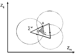
Fig. 1- Illustration of trajectory of plasticity convex at shakedown in the Z space
In our fatigue model we suppose that fatigue corresponds to the limit of elastic shakedown possibility of the material of the structure. This hypothesis implies that fatigue will not occur if elastic shakedown happens at both scales, macroscopic and mesoscopic scales. The local plastic dissipation, which must be bounded, corresponds to fatigue initiation energy. The number of cycles necessary to dissipate this energy corresponds to the initiation period. In the following we shall suppose moreover that this limit depends of the hydrostatic tension occurring during the loading cycle. This hypothesis is not in contradiction with classical concepts used in plasticity theories which suppose that plastic slip is independent of hydrostatic pressure, because we consider the limit of possibility of shake down which may depend on the hydrostatic pressure. Let us recall that Rice-Tracey [6] or Gursons criteria [7] for ductile fracture depend on shear, but also on hydrostatic tension.
From a theoretical point of view, this fatigue modelling permits to answer to a fundamental question: what is the difference between monotonic loading rupture and fatigue and why cycling is necessary to obtain fatigue failure.
4. High cycle fatigue
In high cycle fatigue the loadings are usually not very important, and the structure is globally elastic. Therefore, the fatigue failure initiates only in some grains. It is difficult to evaluate directly the plastic strains and the dissipated energy in the grains that will fail. It is more judicious to proceed indirectly by an inverse way: since the fatigue limit corresponds to the shake down limit, one can evaluate the local stress at the stabilized state if these grains are at (or near) the fatigue limit. Starting from the knowledge of Σ(x,t) at a point x of the structure, we derive the local stress σ by constructing the smallest hypersphere containing Σ(x,t), the centre of which corresponds to Σ* = α* - ρ* ≈ ρ*, because it can be shown that Iα*I/I ρ*I<<1. Thus we have an estimation of the local stress tensor σ(t)= Σ(t)+ ρ(t) in grains which may fail by fatigue.
Different fatigue criteria can be formulated based on the stabilized stress tensor.
- for instance a linear combination of the shear and the concomitant hydrostatic pressure p, τ+ap< b. (Dang Van);
-Papadopoulos criterion, k*+apmax<b can be interpreted in the same way: the radius of the elastic domain at the limit of possible elastic shakedown depends on the maximum hydrostatic tension in the loading cycle.
The different computation steps for the application of the first criterion are the following:
-First evaluate the mesoscopic stress σ(x,t) tensor knowing the macroscopic stress cycle Σ(x,t); this can be done under the assumption of elastic shakedown near the fatigue limit by constructing the smallest hypersphere surrounding the macroscopic loading path. Different algorithms can be used.
- Second, one must consider the plane on which the set (τ(t), p(t)) is maximum relative to the criterion. This computation can be done as follows:
The maximum local shear stress at any time t is given by τ(t)= Tresca (σ(t))=max| σI(t)- σJ(t)|
The stresses σI(t), σJ(t) are the principal stresses at time t.
-The quantity that quantifies the danger of fatigue occurrence is defined by d= max [τ(t)/(b-ap(t))], d is calculated over a period, and the maximum is to be taken over the cycle.
Determination of the parameters a and b can be easily done with classical fatigue tests. The knowledge of two independent fatigue limits (at least) are needed, for instance the rotating bending f and alternated torsion fatigue limit t. Then a and b are given by: a= 3(t – f/√3)/f, b = t.

Fig. 2- Illustration of the main steps for the application of Dang Vans criterion
5. Low cycle fatigue
In this regime, because the mascroscopic plastic strain may be important, so that the differences between macroscopic and mesoscopic quantities become less and less marked. To characterize damage phenomena which occur in the grains, any macroscopic parameter could be chosen. However, the stress is not a good choice because a small variation of stress may induce a large variation of strain and dissipated energy. The deformation is more appropriate, particularly the plastic strain. This parameter becomes popular thanks to the works of Manson and Coffin who propose to use the plastic strain amplitude to correlate the life duration of their test specimens submitted to tension compression loadings. However we propose to choose the dissipated energy because it is a scalar parameter with a clear physical meaning, easy to compute in multiaxial situations (particularly in presence of thermomechanical loadings), and which leads to good predictions on structures. Let us notice, that for general cyclic loading paths, there is (on the contrary to uniaxial loadings mentioned previously) no evident relation between the amplitude of plastic strain and dissipated energy, and therefore the choice between dissipated energy and plastic strain amplitude as fatigue parameter is not neutral.
6. Applications to high cycle fatigue
Three applications will be done which permits to present some aspects and advantages of the proposed theory. However, it is noteworthy that many other examples exist which are not discuss in this presentation. In particular the application of the previous criterion to the prediction of fatigue induced by contact between solids is studied in the following reference [9].
6.1. Fatigue limit of notched specimens
The high-cycle fatigue design of structures in the presence of stress concentrations areas (holes, notches, indentations ) is still difficult and the way to take account of these defects is particularly important. In the current industry approaches, it is carried out by semi-empirical corrections requiring a large number of tests and which domain of validity must be carefully delimited. The most common approach is based on the concept of stress concentration factor Kt, defined as the ratio of the maximum stress at the notch evaluated under the assumption of a purely elastic behavior and the nominal stress. However, the fatigue limit of a notched specimen is different from that of the smooth specimen divided by kt, which led engineers to introduce the concept of fatigue strength reduction factor kf. This coefficient is however not general. In the presence of residual stresses, the correction factor previously determined for a particular load, a particular material, will be no longer valid for another load or another material. Various proposals of empirical corrections exist; they require tests database which are used to carefully delimit the validity range of the proposed factors. Another way to take account of the effects of stress concentration is the use of theories of critical distances based on elastic stresses. Depending on the specific form of these theories, the relevant stresses for fatigue analysis are estimated at a certain distance from the notch (point method) or averaged along a line (line method) or along an area (area method). However, these approaches are inefficient in case of multiaxial loadings. In the following we demonstrate the efficiency of the proposed modelling for the prediction of the fatigue limit of notched specimens by calculations associated with an adequate choice of the representative volume element (RVE).
Let us recall that in the proposed approach, it is supposed that fatigue will not occur if elastic shakedown is possible at both macroscopic and mesoscopic scales. This hypothesis implies that the stresses are near the fatigue limit (but below this limit) and that the macroscopic stress Σ in the RVE becomes purely elastic after a certain number of cycles. Therefore it exists a stabilized residual stress R (due to plastic deformation near the notch) so that Σ(t) = Σel(t) + R is a pure elastic stress state. The mesoscopic stress is then given by:
Σ(t) = Σel(t) +R +ρ (4)
In order to check the validity of this proposal, elastic-plastic simulations are performed and calibrated with tests on smooth and notched specimens made of 42CrMo4 steel (Re=928 MPa, Rm=1024 MPa) subjected to tension-compression with or without mean value, to rotating bending and to alternated torsion. (Details of specimen tested and elastoplastic calculations and corresponding results are given in [10]). The obtained fatigue limits are the following, where Sa is half the stress amplitude and Sm is the mean stress of the same nature:
Tension, kt=1, Sa = 508 MPa, Sm = 0
Tension, kt=1, Sa = 467 MPa, Sm = 400MPa
Tension, kt=2, Sa = 252 MPa, Sm = 500 MPa
Tension, kt=3, Sa = 220 MPa, Sm = 0
Tension, kt=3, Sa = 165 MPa, Sm = 500 MPa
Torsion, kt=1, Sa = 320 MPa, Sm = 0
Bending, kt=1, Sa = 540 MPa
Bending, kt=2, Sa = 267 MPa
Bending, kt=3, Sa = 180 MPa
The methodology used to check the validity of the proposed theory is based on the following features:
1. cyclic elastic-plastic finite element simulations to calculate the stabilized mechanical state with different meshing refinements;
2. use of the Dang Van fatigue limit criterion associated with a material representative volume (critical volume);
3. use of an optimisation process coupling simulations and experiments to determine the critical volume. This volume is determined as the one which permit to obtain the best correlation between calculated fatigue limits and experimental ones for all the tests.
The obtained results represented on Fig. 3 show that a critical layer of 100 microns is suitable.In this regime, because the mascroscopic plastic strain may be important, so that the differences between macroscopic
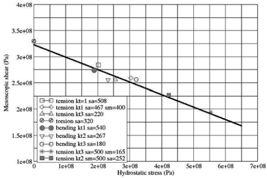
Fig. 3 - Fatigue limit of notched specimens tested with a critical layer (VER) of 100 microns
6.2 Fatigue strength of crankshaft
In this example, it is shown that the proposed fatigue modelling permits comprehensive design to prevent the occurrence of fatigue failure on an automotive engine component, the crankshaft. Crankshafts are designed for «infinite» life and the validation procedures use full load bench tests during hundreds of hours. This component is made of nodular cast iron or forged steel. The critical areas, filets between bearing and flanges, are reinforced by pressure rolling or thermal treatment such as induction quenching or nitriding.
For the fatigue assessment of a component with local reinforcements, a comprehensive approach is necessary. In the case of pressure rolled crankshaft, this means;
- simulation of the pressure rolling operation to calculate the local plastic stress and strain, i.e. the initial residual stress field.
- simulation of the residual stress evolution to a steady state under the service loading
- a fatigue strength calculation taking into account this history.
An example is given for a forged steel crankshaft, with a bearing diameter of 50 mm, and a filet radius of 1.35 mm and of depth 0.5 mm. The pressure rolling is performed with a roller 1.35 mm in radius, and an applied force of 9000 N.
Simulation of pressure rolling: Pressure rolling is modelled with a direct stationary method [11]. The main feature of the method is that the analysis of the rolling is performed in a (r, q, z) axis system tied to the moving load applied by the roller. In steady stage regime, and for a constant angular rate w of the roller, the physical values no longer depend on time but on their angular position in the direction of rolling.
After the first iteration, the mechanical fields are reinitialized upstream of the load, and this double loop (projection - initialisation) is repeated until the yield criterion is satisfied and the stationarity condition [ep (upstream, z) = ep (down stream, z)] is met. This method directly yields the stabilized mechanical state after repeated rolling. This procedure is preferred to the usual finite element method, with incremental translation of the load, which requires large computer memory and very lengthy calculations.
In the present case, the residual stresses are calculated. High values of residual stresses are induced by this mechanical treatment, about –400 MPa in the three directions on 1.5 mm depth. This is the consequence of the high contact pressure, which generates a strong triaxial loading, with a high hydrostatic pressure, and a relatively minor deviatoric effect.
The calculated values are in a reasonable agreement with X-Ray measurements of the residual stresses, at the surface.
Relaxation of residual stresses: The state of the residual stress after the rolling operation will evolve under the effect of the service loading. To reach this new state, one must find the elastically shakedown state which gives a stabilized residual stress field. This calculation can be done, using the simplified method of inelastic analysis of structures proposed by Zarka [12]. In our case, if we consider the service loading to be a simple alternated bending moment corresponding to the fatigue limit level, we observe only a limited relaxation of the residual stresses.
Fatigue strength under service loading: One usually considers that fatigue improvement by pressure rolling of forged steel can be essentially attributed to residual stresses. Therefore the fatigue assessment of the component is done with the Dang Van approach, using the fatigue data of the material without treatment. The pressure rolling and service history through the stabilized residual stress field is taken into account in the loading path.
The efficiency of the approach is illustrated in Fig. 4, which shows the load path at the critical point for the fatigue limit level found experimentally under alternate bending. The material data necessary for those calculations are E and , a kinematics hardening law derived from a cyclic strain curve and two fatigue limits for the Dang Van diagram.
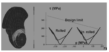
Fig. 4 - Loading path at the critical locus of the crankshaft.
6.3 - High Cycle Fatigue assessment of welded structures: a structural approach
The third example is devoted to present a new way to check the high fatigue resistance of welded structures which find its roots in the proposed fatigue modelling .
Current practice in welded structure design is based on the use S-N curves, hot spot principal stress or structural principal stress limited to specific geometries. However, they are difficult to handle on complex shape components and for multiaxial loadings, which is the case in most of industrial structures. To overcome this difficulty, we come back to the structural approach with a clear definition of the design stress that can be transposed to multiaxial structural problems.
The classical introduction of the design stress is based on the extrapolation of far field stresses with unclear rules. In order to clarify the description of this design stress we propose an approach deriving from an analogy with the concepts, which are at the origin of the Fracture Mechanics. Actually, it is known that the mechanical state in the highly damaged crack tip zone, called by H.D. Bui [13, 14] the process zone, is inaccessible by the usual continuum solid mechanics. In this zone, the material is neither really continuous nor homogeneous and the local strains are not small. Nevertheless, the stress solution obtained from linear homogeneous and isotropic elasticity in small strains allows the correct description of the mechanical state outside of the process zone. Although it is erroneous at the vicinity of the crack tip, it makes sense in terms of an asymptotic solution that allows the correct control and the interpretation of the phenomena produced in the process zone. Likewise, we will look for a way to build the asymptotic solution that allows the correct control and interpretation of the phenomena produced in the critical zone of the weld. For that purpose we adopt an approach with meshing rules taking into account the local rigidity due to the weld instead of the local geometry of the weld itself (as it is the case in Fracture Mechanics, where the actual geometry of the crack tip is not taken into account) that is a very hazardous data. Therefore, the fatigue design can be based on a structural stress calculation from a finite element shell analysis.
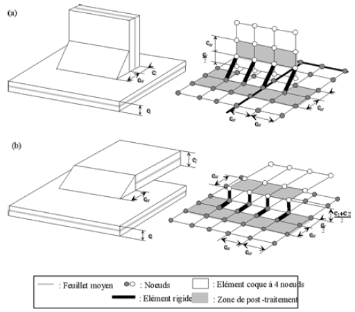
Fig. 5 - Thin shell modelling (a) for fillet weld; (b) for overlap welded joint.
On this basis design rules were established for welded structures [15] with a structural stress, the asymptotic solution, which gives access to the fatigue strength through a unique S-N line where S is a local equivalent stress defined from τ and p at the Hot Spot : τ0=τ-ap, as described hereafter.
This implies the notion of elastic shakedown at all scales, the shakedown at the mesoscopic scale, in the sense of Dang Van criterion can exist only if the elastic shakedown occurs at the structural scale.
From a large data base the Dang Van criterion for welded steel structure is:
τa = a p + b (5)
as shown in Fig. 6.
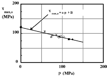
Fig. 6 - Mean fatigue strength at 106 cycles [15].
Fig. 7 summarizes the application of the local approach to predict thefatigue resistance of an engine sub-frame made of a metal sheets joined by continuous welds submitted to out of phase multiaxial loading. For an easier interpretation by the design office, the calculated value of the criterion displayed graphically is the quantity Cd =( τa –(a p + b))/ τa . The failure happens at the predicted locus and fatigue strength can be evaluated.
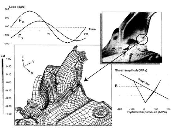
Fig. 7 - Application to engine sub-frame undergoing multiaxial out of phase loading (Courtesy of PSA Peugeot Citroën)
7. Thermomechanical low cycle fatigue application
The difficulty of the thermo mechanical damage simulation comes from the complex steps of the analysis. The modelling of the limit conditions, the choice of the constitutive equations of the material, the numerical strategy, the damage driving force identification and finally the fatigue criterion condition the success of such simulations.
Based on these observations, to be appropriate to the industrial context, thermo mechanical modelling should respect several constraints:
- the necessity to represent the behavior of the material in the structure by simple constitutive equations. Thus, one should favor the representation of the mechanical behavior without coupling with damage. From experience most of the time this coupling is not necessary and does not improve the accuracy of the prediction on structure. Usually it is not necessary to describe the evolution of the structure cycle by cycle and particularly the early stage of the life of the structure. Therefore the identification of the parameters of the constitutive equations can be done on the steady state cycles obtained from material testing.
- the implementation in a finite element code using a numerical integration algorithm for the constitutive law stable and robust enough to authorize large integration steps. Reasonable hypothesis should be introduced in the analysis: the thermal analysis is independent of the mechanical behaviour, the mechanical analysis is not coupled with damage, and the fatigue analysis is based on a stabilised cyclic behaviour of the structure. Thus the objective of the thermo mechanical calculations is to obtain this stabilised fatigue cycle.
A cast iron exhaust manifold of a diesel engine, computed by PSA Peugeot Citroën, illustrates our proposal. Cylinder heads are also calculated by this approach.
The fatigue assessment and the validation are made on a standard durability cycle with a classical engine testing device. The equivalent damage history consists in a succession of full load at 4000 rpm and light load at the same regime. The transient period from full to light load and light to full load takes 30 s and the total cycle takes approximately 700 s. The external surface of manifold is monitored by regular visual inspection to detect crack apparition.
The aim of the thermal computations is the prediction of the temperature field distribution on the manifold from engine data, exhaust gas temperature and mass flow rate, which can already be estimated in the early phases of the project. The thermal computation is performed in two steps. A steady state temperature field distribution is first determined and afterwards the transient response is computed under some assumptions concerning the evolution of the boundary conditions and the evolution of thermal exchange coefficients.
In order to perform mechanical analysis, the constitutive law to characterise the material from ambient to 800°C is needed. At 20°C it presents elastoplastic behaviour, above 700 °C an almost purely viscous one. The fact that one has to deal with a simple unifying law over the whole temperature range is dictated both by the F.E. transient analysis and the short development time constraint. This conducts to the choice of an elasto viscoplastic (EVP) material model. A reasonably representative model of the high temperature EVP behaviour of the material is achieved with a visco elastoplastic constitutive law with six temperature depending coefficients. An important point is to take care of the representative ness of the characterisation tests in the sense of aging and stabilisation of the behaviour corresponding to long-term service conditions.
The FE analysis has been performed in two steps: first the manifold has been screwed on the cylinder head and second a series of thermal cycles have been computed. The imposed temperature distribution was a result of the previous transient thermal calculations. The number of cycles is chosen in order to obtain a stable cycle for the mechanical fields. The results has been analysed in term of dissipated energy per cycle, as indicated in Fig. 8.
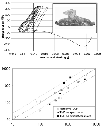
Fig. 8 - Thermo mechanical calculation and stabilization and predicted life versus experimental fatigue life on tested specimens and on exhaust manifolds.
The final objective is to evaluate the fatigue strength, or the lifetime of the structure, from the stabilised response of this structure. Charkaluk and Constantinescu [16] observe that the dissipated energy per cycle at steady state
W= ∫cycleσ : έ p dt (6)
can be representative of the fatigue behavior of a material.
The interest of the dissipated energy per cycle comes from three main points:
this energetic quantity can be easily generalized to multiaxial situation
its determination is dependant of the temperature because it integrates the whole loading path and therefore allows calculations with anisothermal loading.
WS is representative of the cyclic behavior of materials.
The fatigue criterion can be simply expressed by a relationship:
W= c Nβ (7)
The predictivity of the calculation is satisfactory as indicated by numerous comparative results between experiments and calculation on Fig.3.
To take into account the fact that the dissipated energy is based only on the deviatoric part of the stress tensor, it is proposed to introduce the instantaneous hydrostatic pressure in the criterion in order to improve the predictivity of the previous relation when high triaxiality is present [17, 18]
(W + apmaxs)= c Nβ. (8)
8. Conclusions
From theoretical point of view, fundamental questions have still not been answered satisfactorily: what is the difference between monotonic loading rupture and fatigue and why cycling is necessary to obtain fatigue failure. Although many progresses has been done in understanding of physical phenomena, many difficulties still exist to achieve an interdisciplinary consensus in the way to model fatigue crack initiation. Depending on the discipline, points of view are often different. An engineering mechanical approach is presented. In this proposal, fatigue is induced by build up of plastic deformations due to cycling, in a heterogeneous way in the high cycle regime, and in a more homogeneous way in low cycle fatigue. The fatigue resistance in this modelling, corresponds to the limit of the possibility of the material with which the structure is made of to shakedown. This hypothesis implies that the total acceptable plastic work is bounded and consequently the build up of plastic strain and residual stress must be beyond some limit state. Residual stresses correspond to store energy, so that the admissible store energy is bounded too. Thus the shakedown theory gives a general framework to the fatigue analysis, as well as for low cycle fatigue than for high cycle fatigue. Many applications to industrial structures submitted to complex multiaxial loadings are already successfully done, particularly in the automotive industry. The adaptability of this approach should be highlighted, whatever the situation , thermo mechanical loading, contact, residual stresses effect, assemblies a common view is adopted, the fatigue criterion is easy to handle in an industrial context and does not need many informations. As far as the HCF criterion takes into account the multiaxiality of the stress tensor, no adjustable parameters nor corrective coefficients are necessary whatever the situation including contact problems. For LCF criterion the energy description of the damaging parameter allows to solve any problem including the difficult one of visco plasticity behaviour under anisothermal transient loading.
References
[1] H.D.Bui, K. Dang Van,C. Stolz, Relations entre grandeurs microscopiques et macroscopiques, C.R.A.S., Tome 292, Série 2, 1981, pp.1155-1158
[2] Koiter,W.T. (1960), General Theorems for Elastic-Plastic Solids, In Progress in Solid Mechanics, eds. Sneddon, J.N. and Hill, R., 1, North-Holland, Amsterdam, pp. 165-221
[3] Melan, E. (1938), Zur Plastizität des räumlichen Kontinuums, Ing. Arch., 9, 116
[4] Nguyen, Q. S., (2000), Stability and Nonlinear Solid Mechanics, J. Wiley & Sons
[5] Mandel J., Halphen B., Zarka, J.(1977), Adaptation dune structure Elastoplastique à Ecrouissage Cinématique, Mech. Res. Comm.,(4), p. 309-314 [ Links ]
[6] Rice J.R., Tracey, D.M., 1969, On the ductile Enlargement of Voids in Triaxial Stress Fields JMPS, Vol.17, pp.201-217
[7] Gurson, A.L., 1977, Continum Theory of Ductile Rupture by Void Nucleation and Growth: Part I- Yield Criteria and Flow Rules for Porous Ductile Media, ASME J. of Engineering Materials and Technology, Vol 99, pp. 2-15
[8] Dang Van, K., Fatigue Analysis by the Multiscale Approach, High Cycle Metal Fatigue, From Theory to Applications, C.I.S.M. Courses and Lectures N° 392, Ed. Ky Dang Van & Ioannis V. Papadopoulos, Springer 1999 pp.57-88
[9] Dang Van, K., Maitournam, H.M., Rolling contact in railways: modelling, simulation and damage prediction, Fatigue Fract. Engng. Mater. Struct., Vol. 26, 2003, pp. 939-948
[10] Maitournam H.M., Dang Van K., Flavenot J.F., Fatigue design of notched components with stress gradients and cyclic plasticity, 12th International Spring Meeting, Paris, May 20-22, 2008, JIP 2008
[11] K. Dang Van, M.H. Maitournam, Steady-State Flow in Classical Elastoplasticity: Application to Rolling and SlidingContact, J. Mech.Phys.Solids, 41, 11, 1993, 1691-1710
[12] J. Zarka, Direct analysis of elastic-plastic structures with overlay materials during cyclic loading, Int.J. Meth. In Eng., Vol.15, p.225
[13] Bui, H.D. Problèmes généraux de croissance de fissure. Partie I, approche de lendommagement. Revue française de Mécanique, Vol. 4, (1983), pp. 3-7
[14] Bui, H.D., Dang Van, K. Some recently developed aspects of Fracture Mechanics. Nuclear Engineering and Design, Vol. 105, (1987), pp. 3-12
[15] Fayard, J.L., Bignonnet, A., Dang Van, K., Fatigue Design Criterion for Welded Structures, Fatigue Fract. Engng. Mat.struct. 19 (1996), pp.723-729
[16] E. Charkaluk and A. Constantinescu. Energetic approach in thermomechanical fatigue for silicon molybdenum cast-iron. Materials at High Temperatures, 17, (3), 2000, pp. 373-380.
[17] A. Constantinescu, K. Dang Van, H.M. Maitournam, A unified approach for high and low cycle fatigue based on shakedown concepts, Fat. Fract. Engng. Mat. Struct., 26, (2003) pp.1-8
[18] S. Amiable, A. Constantinescu, S. Chapuliot, A. Fissolo. Prédiction de durée de vie des structures sous chargement de fatigue thermique. 17ème congrès de Mécanique, Troyes sept. 2005
